0
\$\begingroup\$

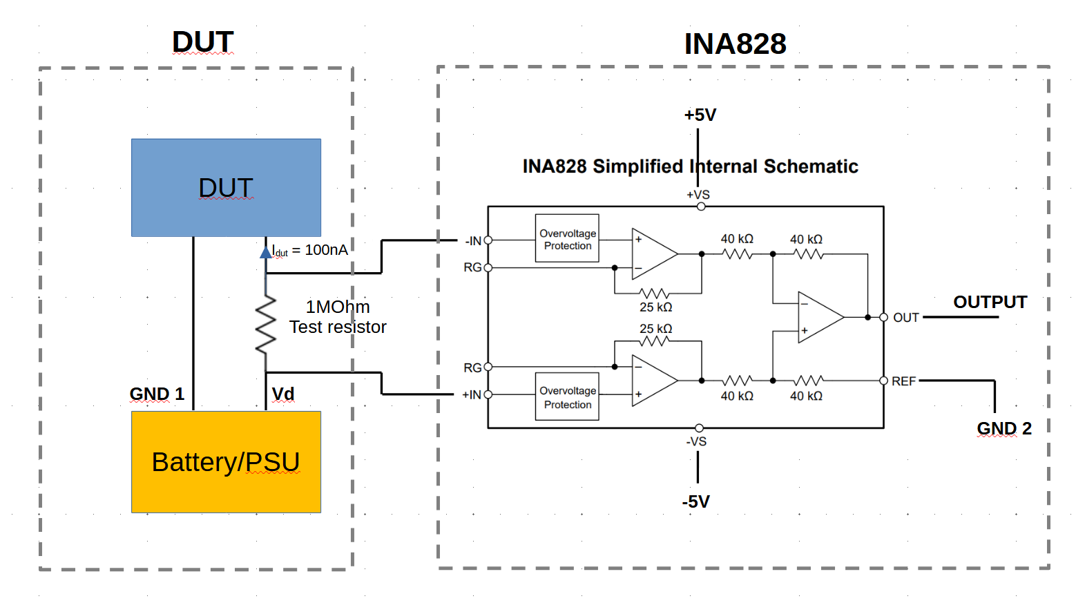
I need to measure the voltage drop across a test resistor in order to sense the current flowing through it. This test resistor has a value of 1 MOhm and it's connected between the positive voltage of a battery (or PSU) and the positive input bias pin of a DUT. The ground pin of the battery (GND1) is connected directly to the ground pin of the DUT (GND1). The current flowing in the resistor is around 50nA to 100nA, thus the voltage across the resistor is about 50mV to 100mV.

I cannot connect directly the test resistor to an ADC to measure the voltage drop across the resistor because the ADC has a low input resistance. I am therefore thinking of using the INA828 between this test resistor and an ADC (for instance the ADS1263).

I am hence thinking to realize something like the schematic below. The ground of the circuit containing DUT (GND1), battery and test resistor will not be common with the ground of the INA828 (GND2) and subsequent ADC. I have some questions:

  1. Do you think the schematic is correct or am I making any mistake?
  2. Is the INA828 a good choice for measuring these voltages or you have a better suggestion? My guess is that it should work well since the input bias current is 0.15nA thus negligible compared to the current flowing in the test resistor.
  3. Do you agree with using a dual supply +/- 5V and to connect the REF pin to ground?
  4. Will I need to use an ADC compatible with dual supply? My guess is that, since the current between battery and DUT will flow only in one direction, the output of the INA828 will be always positive. Or am I wrong?

Thanks in advance

Schematic of the Sensing resistor and INA828

\$\endgroup\$

2 Answers 2

3
\$\begingroup\$

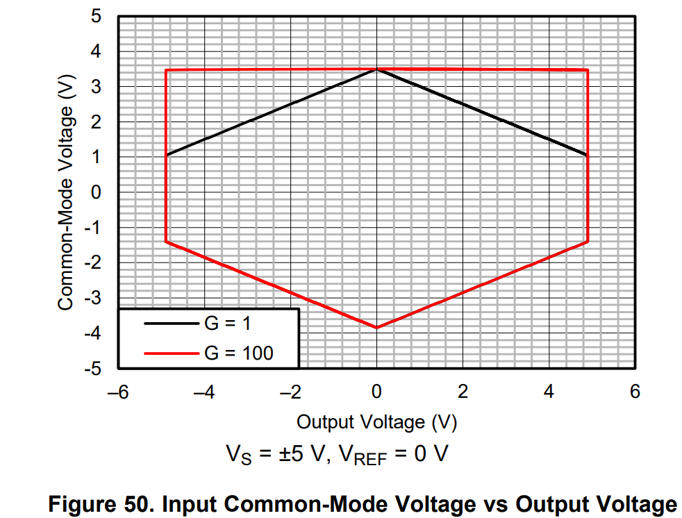
From the IN828 datasheet we have this (in your case G=1 so the black diamond):

enter image description here

You need to stay within the 6-sided diamond figure.

If the highest possible output voltage is +/-100mV then you need to keep GND2 and (Vd-I*R/2) within about +/-3.5V of each other. If it is +/-3V then more like within +/- 2.5V of each other. It's up to you to maintain that relationship, and if you don't the amplifier will not work properly (it will saturate in one way or another).

Floating the entire front and circuit and using optical or other means to transmit the signal, as Andy suggests, is a possibility (maybe the only practical one, depending on your situation) but it comes with many possible complications. You still have to maintain the common-mode voltage as shown in the figure (so maybe you need a direct connection to Vd or a buffer amplifier to maintain the CM input voltage as with bio signals) and if you use something more pleasant than batteries such as a DC-DC converter it could disrupt the measurement due to AC noise and capacitive coupling. The means of transmitting the signal could also disrupt the measurement. A nA signal, while not inherently difficult to measure, could be challenging to galvanically isolate.

One off-the-shelf possibility might be a battery-powered DMM with serial interface, but there will still be some coupling through the interface which could disrupt the measurement. COM for the meter would best be connected to Vd, most likely, depending on your setup.

\$\endgroup\$
5
  • \$\begingroup\$ Thanks for your very detailed answer. How would I implement a circuit that can always keep GND2 and (Vd-I*R/2) within about +/-3.5V of each other as shown in the figure you posted? I have used so far a low cost digital multimeter, but my understanding is that even more expensive ones have an input resistance that is not high enough, thus affecting the measurement. Do you think using a battery powered multimeter would be better that using the INA828? \$\endgroup\$
    – spanito
    Commented Nov 16 at 18:30
  • \$\begingroup\$ You would need to describe your actual setup in some detail in order for me (or anyone else, I suspect) to give a sensible answer to that. The 200mV voltage range on a typical DMM is actually a nA range if you look at it sideways. With a 10MΩ input resistance it is 19.99nA full scale. You could parallel the 10M (assuming that's correct) resistance on the same voltage range with nominally 10/9 MΩ to make it +/-199.9nA full scale. \$\endgroup\$ Commented Nov 16 at 19:46
  • \$\begingroup\$ I use a 3.7V LiPo battery that provides Vd and GND1 to a PCB with multiple sense Resistors with 0.1% tolerance and a bypass. Sense Resistors can be enabled/disabled with Jumpers. The DUT is an Attiny85 or a TPL5110. I initially select the bypass to start the DUT, I put it in deep sleep and then select the appropriate sense resistor. I believe that at nA current levels the DMM input resistance is not high enough. Hence I was looking for a buffer or OPA with very high input DC resistance. I do not need to log the data to a PC or other device, so a DMM with an LCD display is enough for me. \$\endgroup\$
    – spanito
    Commented Nov 17 at 3:03
  • \$\begingroup\$ I have modified the post adding a second proposal of the circuit. This will ensure that the difference between common mode voltage and output voltage will be only few hundreds of mV and should avoid saturation in the INA828. Do you think this would actually work? \$\endgroup\$
    – spanito
    Commented Nov 17 at 11:31
  • 1
    \$\begingroup\$ I'm sorry @spanito but I'm returning (rolling-back) the question to how it originally stood. Once you have received answers you should not amend your question without checking that the amendment doesn't make given answers look stupid. I suggest you start a new post and open up a new question to the whole floor. \$\endgroup\$
    – Andy aka
    Commented Nov 17 at 11:37
2
\$\begingroup\$

The ground of the circuit containing DUT (GND1), battery and test resistor will not be common with the ground of the INA828 (GND2) and subsequent ADC.

The whole scheme depends on knowing how the two disparate ground systems interact (if you are to rely on a measurement that involves a galvanic connection to the measurement amplifier). For instance, if the two grounds wobble with respect to each other at 10 volts p-p at some frequency then it's extremely likely that your measurement system will fail due to excessive common mode interference exceeding the InAmp supply rails.

Of course, your two disparate grounds could have 1,000 volts between them and this is a real problem. So, unless you can resolve this, all four of your questions are invalidated.

If this cannot be resolved then I suggest you use an isolated measurement method. This might mean battery powering a "front-end" circuit that locally monitors that current through the resistor and transmits that information optically (or via radio) to the main measurement circuit powered remotely. This is a real option.

\$\endgroup\$
6
  • \$\begingroup\$ Thanks for your fast response. My idea was to power the INA828 via battery as well. But it will be a separate battery, not the same used for powering the DUT and sensing resistor. For instance using two 9V batteries to get +9V, -9V and then using a positive LDO and a negative LDO to convert to a "stable" +5V, -5V. Not sure if the LDOs are really necessary though. Do you think I will still have issues with grounding? \$\endgroup\$
    – spanito
    Commented Nov 16 at 16:45
  • \$\begingroup\$ @spanito there will be some form of ground on the measurement side so, unless your ADC and associated digital system and any wiring are fully galvanically isolated from ground/earth you will have problems. \$\endgroup\$
    – Andy aka
    Commented Nov 16 at 17:04
  • \$\begingroup\$ I see, thanks. It's not clear to me how would you implement the "front-end circuit" that you mentioned above. Do you mean to use an isolated amplifier instead of the INA828 and then connect the output of the isolated amplifier to the ADC? Something like the "AMC1411-Q1" from TI would be fine? \$\endgroup\$
    – spanito
    Commented Nov 16 at 17:34
  • \$\begingroup\$ You could do that or use an opto coupled ADC feeding a digital stream from the DUT side @spanito \$\endgroup\$
    – Andy aka
    Commented Nov 16 at 17:39
  • \$\begingroup\$ I have modified the post adding a second proposal of the circuit. This should solve the problem caused by the two different grounds. Do you think this would actually work? \$\endgroup\$
    – spanito
    Commented Nov 17 at 11:32

Your Answer

By clicking “Post Your Answer”, you agree to our terms of service and acknowledge you have read our privacy policy.

Not the answer you're looking for? Browse other questions tagged or ask your own question.