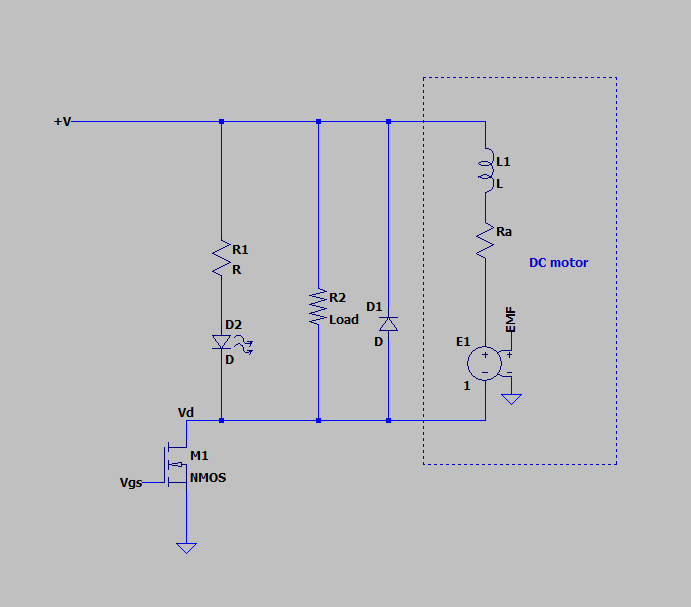
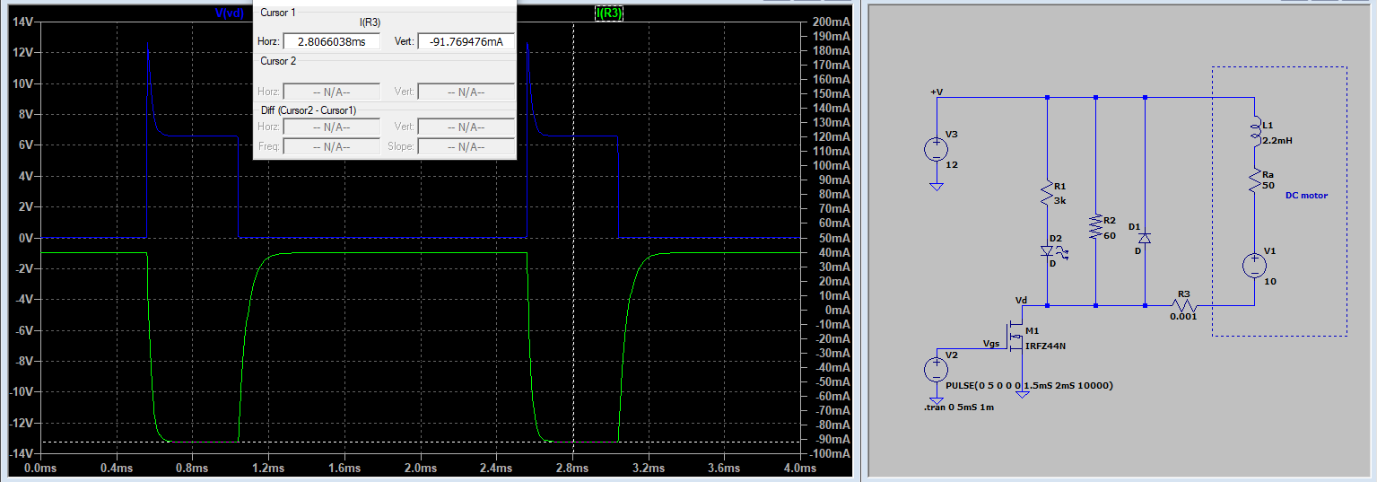
In a student lab project, we tried to drive a DC motor from FAULHABER Schöneich 2230V024S (148) and a reductor 81:1 22B (298) 2-16V L=35uH, see the 024S variant in the datasheet, consuming about 600mA at 12V during normal operation (driving a pendulum). We soldered the Schottky diode SB260 (=SR260) 2A/60V directly across the leads of the motor as a flyback bypass.
We use a PWM signal from the uC (Arduino uno) powered through its USB connection to a hub and a Raspberry Pi-3. This is a very common and largely discussed setup with an N-MOSFET as a low-end switch, and I didn't expect any caveats. However, since the ground of Pi3+hub+uC is isolated, I decided to add an optocoupler, which seems to be also a very commonly used solution (see the figure below from https://bestengineeringprojects.com/interfacing-optocoupler-with-arduino/, cf EE.SE question MOSFET switch using an optocoupler),
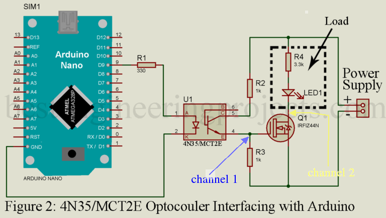 arduino-optocoupler-interfacing-osc-768x435.png
Available also as a breakout board from Robotdyn
with IRF540N (and an external flyback Schottky diode, see its supposed schematics on https://forum.arduino.cc/t/mosfet-power-module-and-optocoupler/508996). We have tried both of them. Our power is taken from a stabilized 12V lab voltage source, and
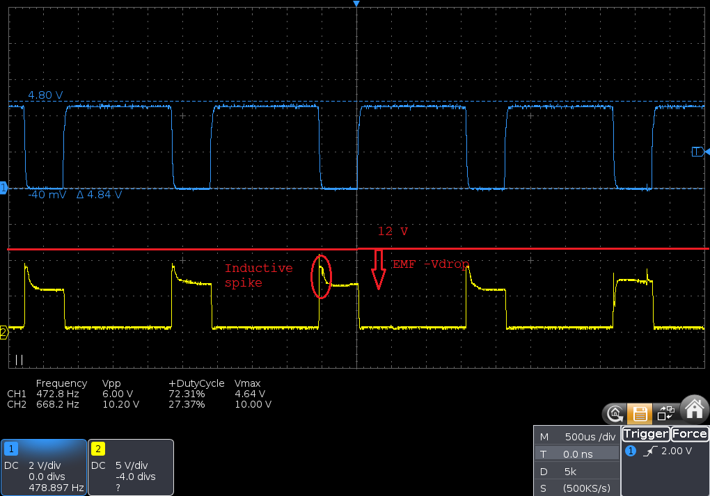
our R2=R3=R4=1K. As an additional test load, we use a brushless 12V PC fan. In further tests, we replaced the uC with a square signal from a function generator at 470 Hz allowing duty cycles from 15 to 85% (nb: the standard Arduino library call uses a PWM frequency of 490Hz). Our scope is attached at the gate (channel 1) and the drain (channel 2) as shown in the schematics below.
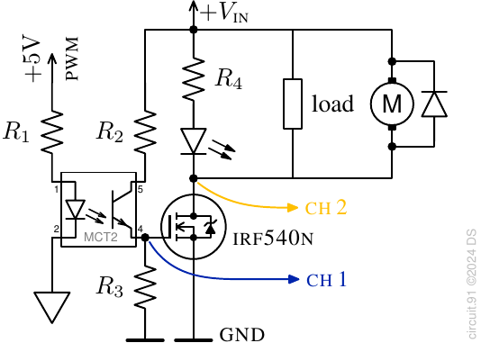 In all cases, we ended up with similar observations illustrated below.
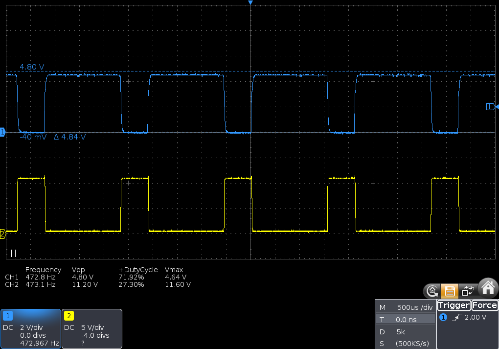 no load (LED only) PWM-GBF-470-0load.png
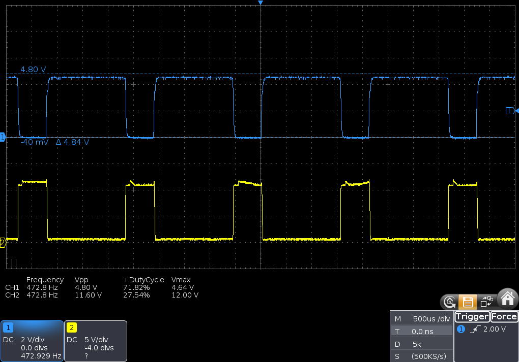 resistive load (brushless fan) PWM-gbf-470-Rload.png
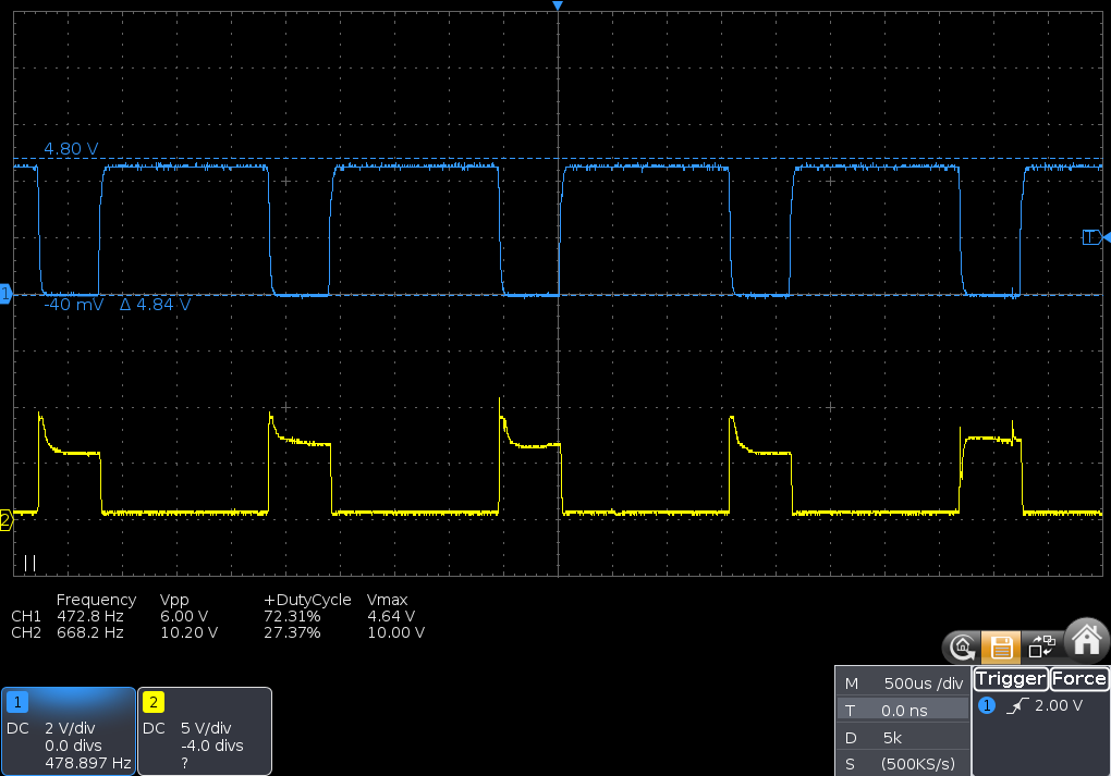 resistive + motor PWM-gbf-470-LRload.png
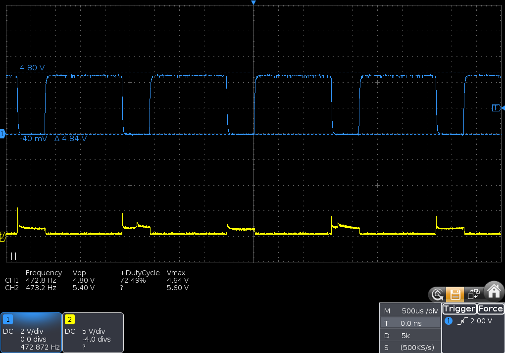 motor only PWM-gbf-470-Lload.png
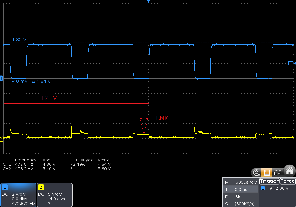
All works as expected for resistive loads: when the gate is high (5V), the FET closes (i.e., lets the current flow from its drain to the source), and channel 2 drops to 0 (ground). However, when the motor (= inductive, or more correctly -inertial, see the answers) load is added in parallel, things go south, and driving the motor alone (last picture) turns into a disaster: For some reason, despite the flyback diode, the voltage at the drain is low as if the FET remained almost totally closed, even when our gate is kept at 0V!? I cannot see exactly why.
With an additional ohmic load (second last figure), the FET appears sort of half-closed. The voltage at the drain (ch 2) during off time also depends on the duty cycle: 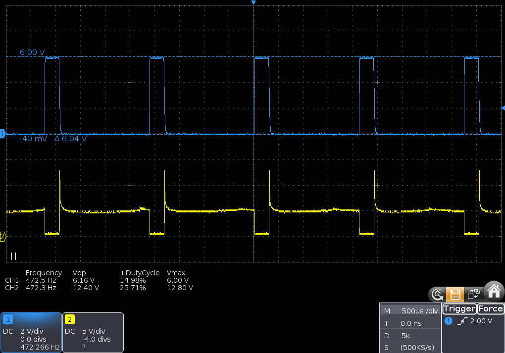 (pwm-gbf-470-15duty-Lload.png 15% duty cycle, Vgs=6V, motor only).
The FET appears to open more for shorter cycles as if something gets saturated during longer cycles (the two last plots differ in their duty cycles).
Question(s):
Explain this circuit and the case of the function generator (Note 1).
Suspecting that what we have is not a bug but a feature, i.e., this is how things are supposed to run, how can we achieve our goal of controlling the speed of that motor in a most simple and adequate fashion? Can our setup be salvaged somehow through some few additional elements or another circuit/strategy imposed?
In this context, let me recapitulate our situation:
we want to use our uC (Arduino) for one-directional speed control of a small classic permanent magnet DC motor operating between 0 (preferably, or 5) and 12V (optionally, up to 15) and consuming around 100-500mA.
The motor is almost freewheeling unopposed, i.e., mechanical resistance (load) is very low, and braking, if necessary, should occur through other means.
Furthermore, while the 81:1 gearbox reduces the speeds to around 50 rpm, the motor itself runs at 4000 and has significant kinetic energy and back-EMF.
uC-wise, the most direct and frequently used output at our disposal is the 5V PWM with frequencies from about 500 and up to 10kHz and 8-10 bit duty cycle resolutions.
thinking of potential future use of these setups by students, we prefer to isolate the signal side (uC and computer) through an optocoupler.
for the same reason, despite that in the lab, we do have easy access to stabilized positive and negative rail DC power, we like to keep the supply as simple as a small 12-24V 2A DC adapter.
we are, obviously, not electrical/electronic engineers ...
Note 1: The motor+diode can be driven happily with a 470Hz PWM Vpp=10V signal supplied directly from the amplified function generator without any intermediate circuit. Also, we tried the circuit at higher PWM frequencies with similar results, but the capacitance of the optocoupler or gate (? visible in the pictures, channel 1) becomes more of an issue in that case. In view of the answer by @Bravale, the following test may be interesting.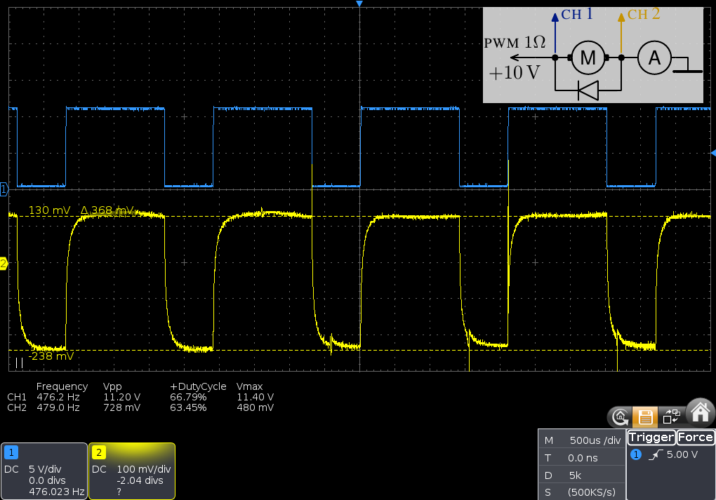 pwm-gbf-470-Lload-GBF-circuit.png. Here we added a benchtop amperemeter in the true-rms AC mode with shunt resistance of about 0.1 to 10 Ohm between the motor and the ground. The impedance of the function generator amplifier is 1 Ohm; the DMM reading is around 80mA. Unlike in the MOSFET circuit, the motor here remains connected to the mains for all times, and the current (Ch 2) flows during both the duty cycle (+10V on Ch 1) and the "off-duty" period (0V on Ch 1). In the latter case, the EMF from the motor (see @Bravale's answer) seem to discharge in the amplifier?
Note 2: Taking another motor+reductor of the same model, connecting the digital multimeter (DMM) to that motor's leads, and turning it by hand, we can observe EMFs of +/- 5 to 7V DC, depending on the rotation sense and speed. Both senses feel similarly. This seems to agree with the datasheet: that motor alone does max 8000rpm at 24V which is reduced to 100rpm. Our motor is equipped additionally with the snubber diode soldered across its leads. That makes directions (and leads) differ: with DMM's COM at the anode of the snubber ("anode lead"), turning in one direction is easy and produces +5..7V, while the opposite direction is sensibly impeded and produces -100..-300mV. The latter seems to be the voltage drop on the SR260 diode: according to its datasheet, its max forward voltage drop can be 0.7V at 2A, suggesting 200mV at 600mA, which is the typical current that we observe when running this motor+reductor at ~50rpm (so that the motor itself does 4000rpm). The motor is connected to our circuit (in parallel with the LED in the drawing) so that the "anode lead" is at the drain (channel 2 point) and the "cathode lead" is at the Vin=+12V. The "easy" direction of rotation, is the direction in which the motor normally turns when powered up (through PWM, when the FET closes).
Note 3: Following the advice by @D.A.S., we raised the voltage at the gate (Vgs) to 10V by putting R3=1k and R2=220ohm. This, however, seems to produce little difference, from the plot below to the last one before notes.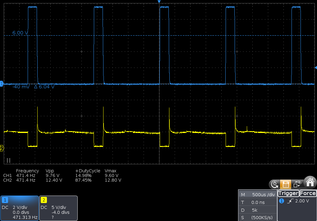 (15% duty cycle, motor only *73duty10V-Lload.png). The phenomenon of the FET appearing more fully "closed" for longer duty cycles persists:
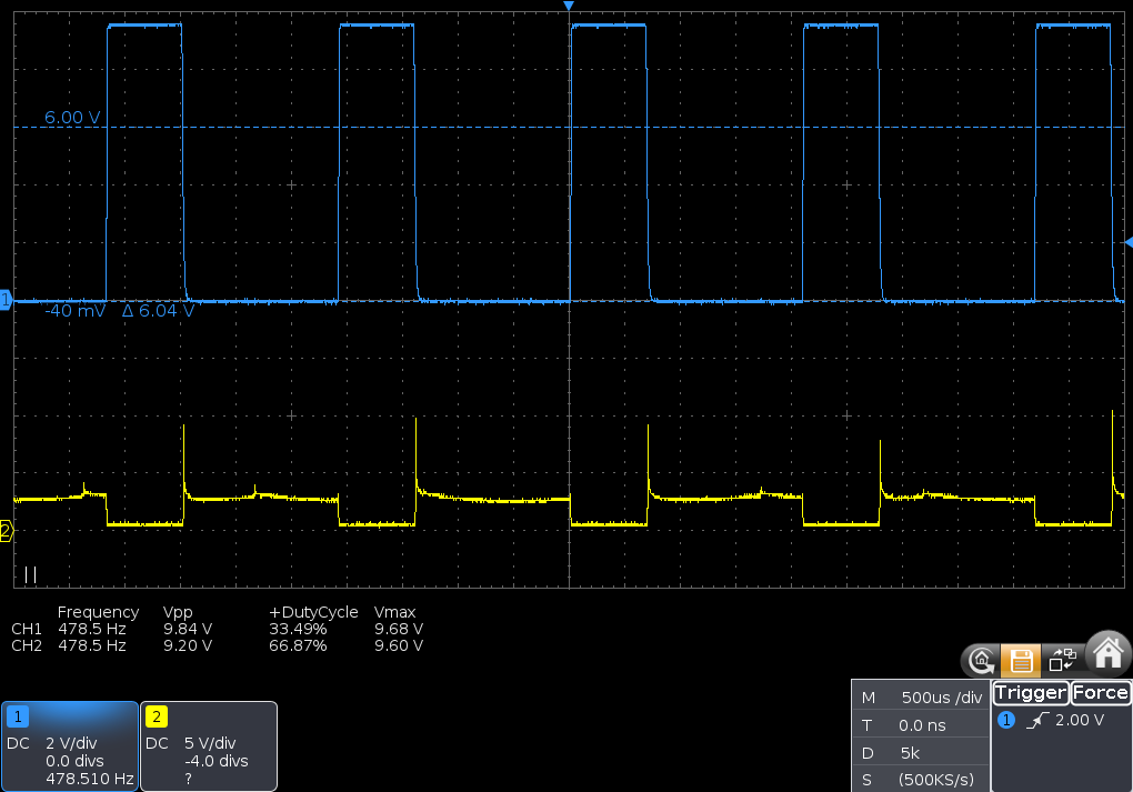 (33% duty cycle, motor only *33duty10V-Lload.png)
 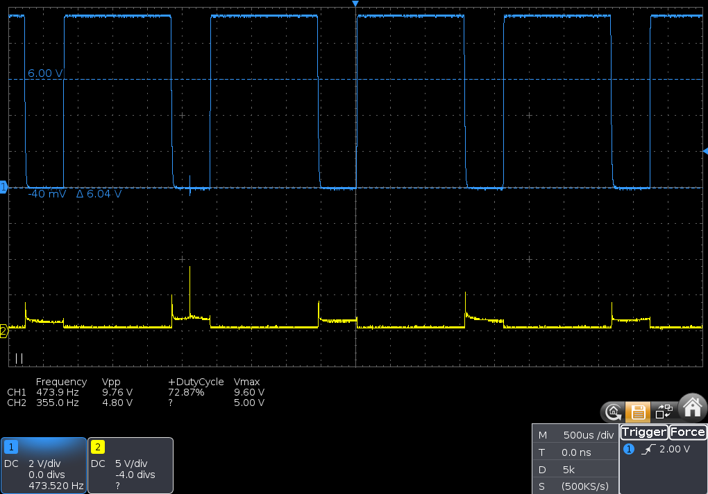 (73% duty cycle, motor only *73duty10V-Lload.png)

