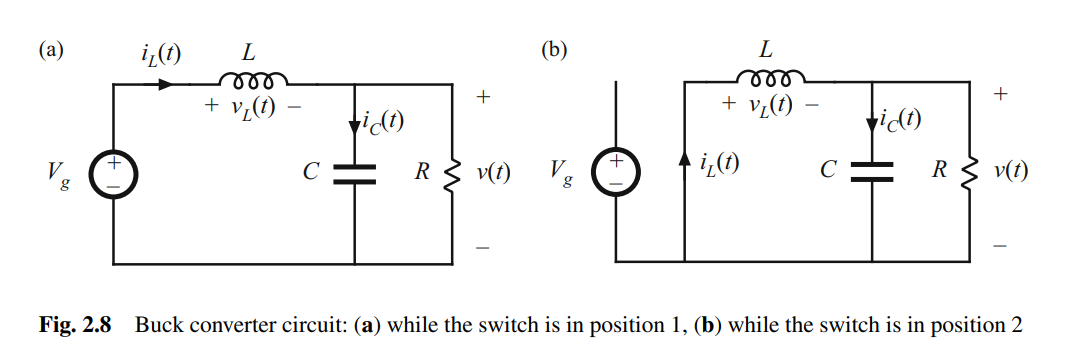
In section (a) in the picture given below, while the switch is conducting the capacitor is charging so the ic= (il) - (v/R). While the switch is not conducting, section b, the capacitor should be discharging isn't it? Based on that I have 2 question as below:
- In both circuits in the picture (a, b) the capacitor current is shown as it is charging because the the way of the current is shown same. Why?
- Considering the capacitor is discharging in (b), ic = (v/R)- (il), is this node equation correct?

Source: https://elprivod.nmu.org.ua/files/converters/Robert_Erikson_fundamentals-of-power-electronics-3n_2020.pdf
