2
\$\begingroup\$

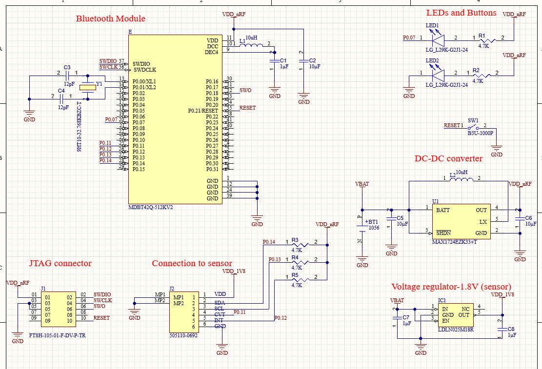
I am encountering a technical issue with a circuit I recently assembled. The circuit includes an nRF52832 microcontroller module (MDBT42Q), a 1.8V voltage regulator (LDLN025M18R) for powering a sensor, and a 3.3V step-up DC-DC converter (MAX1724) to step up the voltage from a 3V coin-cell battery (CR1220) and supply to the whole circuit. Previously, I used a 3V voltage regulator, but I observed a voltage drop to 2.7V and reduced battery life. To address this, I switched to the 3.3V DC-DC converter.

The issue I am having is that, the circuit powers up when the battery is connected but turns off after 2–3 minutes. The circuit can be restarted by removing the battery and reinserting it after some time, suggesting that the battery is not entirely drained. As I am relatively new to circuit design, I am struggling to identify the root cause of this issue.

I would appreciate any suggestions or steps to help debug and resolve this problem. I have attached the schematic.enter image description here
\$\endgroup\$
3
  • 1
    \$\begingroup\$ Button batteries are notoriously poor at supplying peaks of current. What is the expected current consumption of your circuit and, have you measured it. Look at the voltage of the coin cell using a DVM and see how rapidly it falls. \$\endgroup\$
    – Andy aka
    Commented Nov 18 at 17:55
  • \$\begingroup\$ It seems like the module would run at 1.8 V, so you might consider DC-DC stepdown to 1.8V which would lower the drain on the battery. LEDs could be powered from the battery directly, unless they are blue or white. \$\endgroup\$
    – jpa
    Commented Nov 19 at 9:59
  • \$\begingroup\$ @Andyaka according to my calculations, the steady state current would be around 15.7 mA. And during bluetooth data transmission it would peak up to 20 mA. \$\endgroup\$ Commented Nov 19 at 19:02

1 Answer 1

6
\$\begingroup\$

The root cause is, the battery is incapable of powering your circuit.

Even a brand new CR1220 battery has typical internal resistance of 20 ohms, rated current of 0.05mA to 0.1mA, maximum continuous current of 1mA, and typical max pulse operation of 16mA.

Meaning even in theory, short circuit current of the battery will be 150 mA, likely much less.

The switch mode regulator will try to pull 500 mA in peaks out of the battery if necessary to keep the output at 3.3V.

The voltage at regulator input will likely drop below the voltage it can operate.

\$\endgroup\$
3
  • \$\begingroup\$ Hi, I was wondering what should I do in this case to power up my circuit. I want to make the board small (right now the board is 4 by 5 cm) so I want to find a battery that would be suitable for my circuit and at the same time would take up less space. It would be great if you could suggest me possible solutions. \$\endgroup\$ Commented Nov 19 at 18:38
  • \$\begingroup\$ You need to know how much your circuit consumes and find a battery that can provide that current. Then define how long you want it to run so then you know what capacity you need. \$\endgroup\$
    – Justme
    Commented Nov 19 at 19:33
  • \$\begingroup\$ The continuous current consumption for my circuit would be around 15.7 mA. And during active data transmission it would peak up to 20 mA. I need it to run for at least a whole day. \$\endgroup\$ Commented Nov 19 at 19:54

Your Answer

By clicking “Post Your Answer”, you agree to our terms of service and acknowledge you have read our privacy policy.

Not the answer you're looking for? Browse other questions tagged or ask your own question.