0
\$\begingroup\$

I'm not an electrical engineer, but i love to learn about electronics.
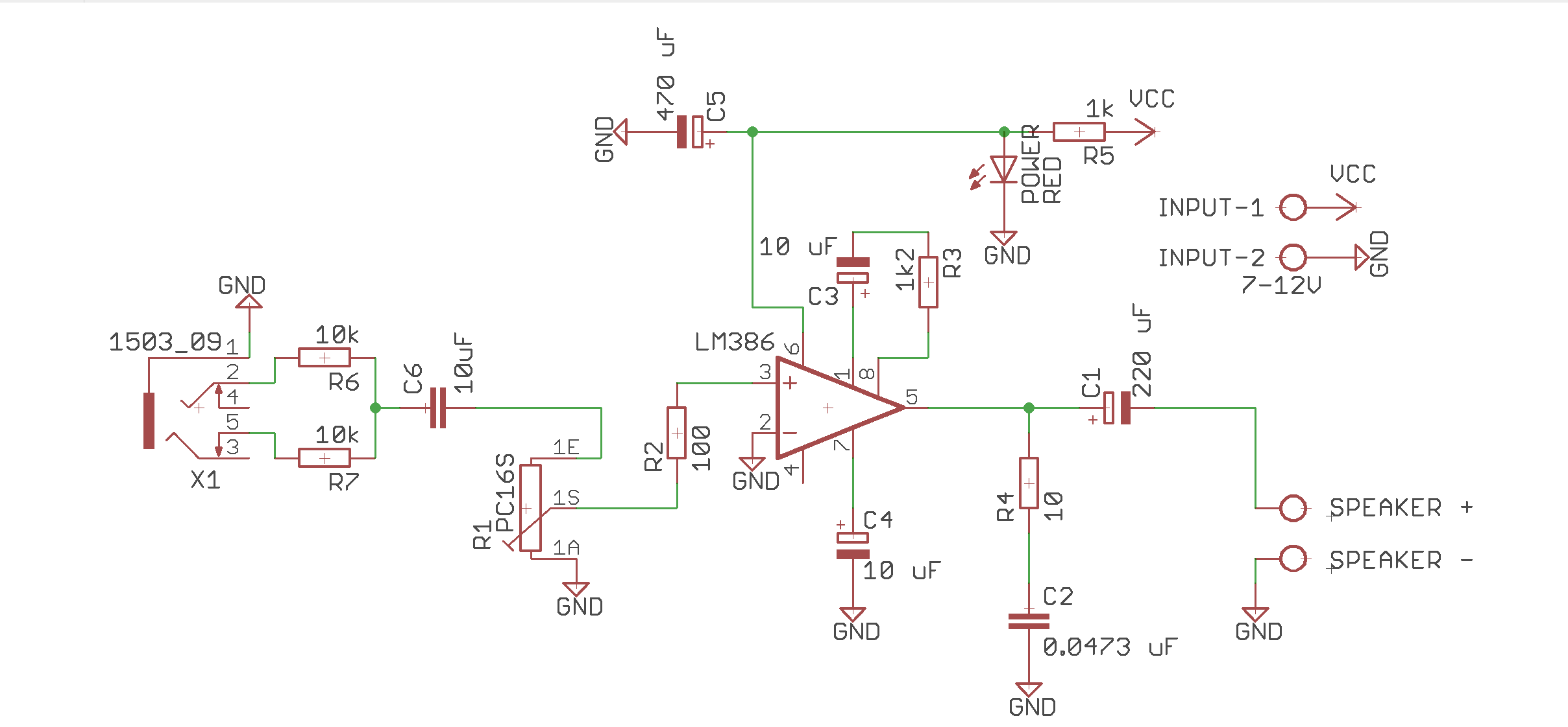
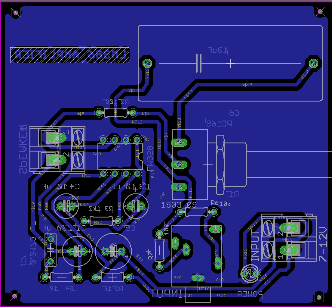
So i try to make LM386 amplifier circuit to a PCB which can be connected to smartphones, mp3 players or other devices that have a 3.5mm jack. The circuit design that I made is shown in the picture below.

LM386 AMP SCHEMATIC

LM386 PCB DESIGN

The problem I'm having is that when I connect it to a 9V battery, the red LED lights up and I assume all the components in this circuit are working properly. However, when I connect the output part with an 8 ohm 1W speaker and connect the input part with a 3.5mm jack connected to my smartphone, the speaker connected to the PCB that I made cannot produce any sound at all. I try to analyze it one by one but i have no idea which part is not working or part that not connected properly. I wonder if this problem is related to the circuit design that I made.

Any solution would help me to develop this circuit and my knowledge about electronics.

\$\endgroup\$

1 Answer 1

4
\$\begingroup\$

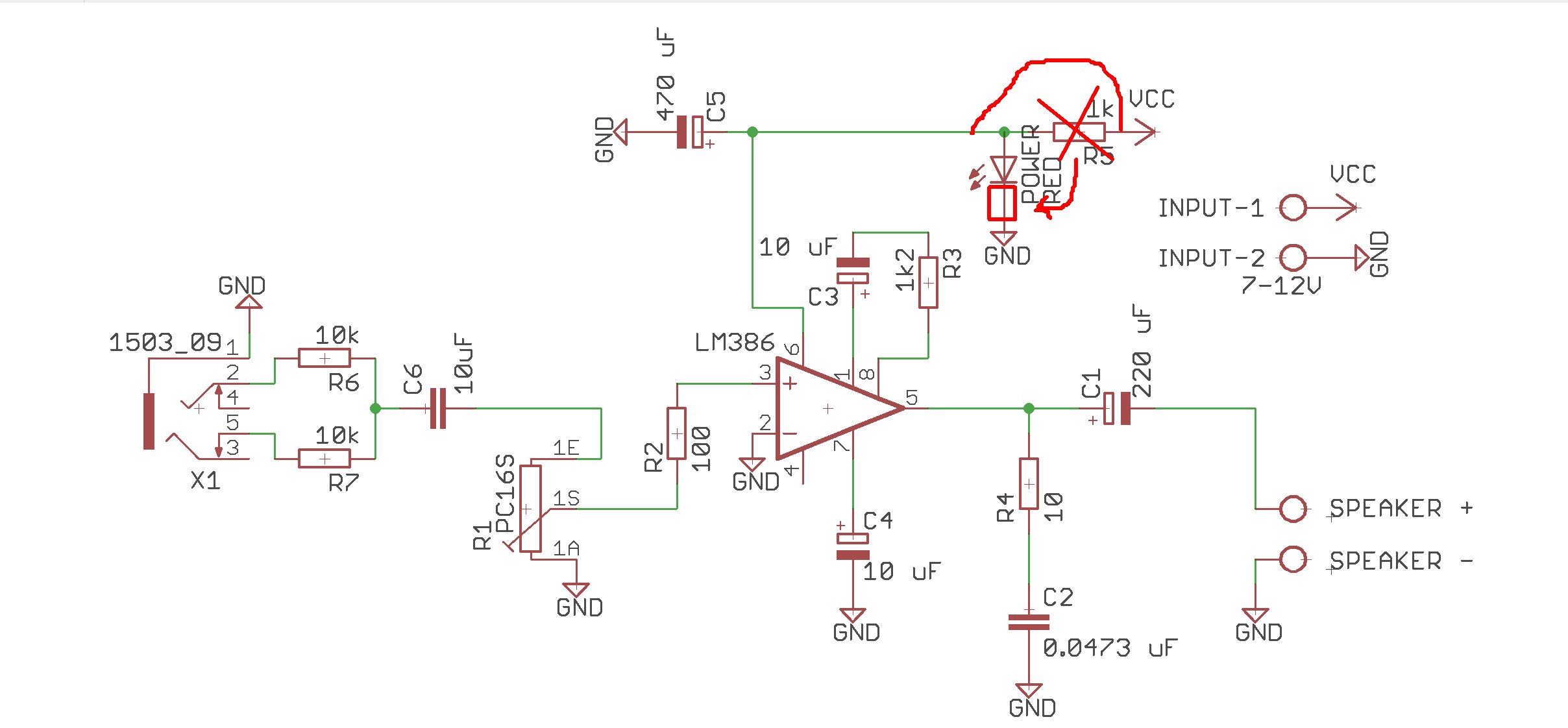
R5 seems misplaced. With 1 kΩ in series with your amplifier, you are limited to a few mA of consumption, which is about what it takes in standby.

Move R5 away from your Vcc input to only be in series with your LED, not your amplifier.

enter image description here

\$\endgroup\$
7
  • \$\begingroup\$ Oh i didn't realize that!, Placing the R5 in series with LED would deliver more current to amplifier? i think thats why i check the output pins from LM386 with multimeter only showing 1.6-1.8 V \$\endgroup\$
    – Fish_EL
    Commented Nov 20 at 12:31
  • \$\begingroup\$ @Fish_EL Sort of, but don't think in terms of "delivering" more current. Your amplifier has voltage input and pulls as much current as it desires. Your resistor is preventing it. A current source on the other hand would push or forcefully deliver current. A voltage source would only supply as needed. In your schematic, does 0.0473 uF actually mean 4.7 uF? \$\endgroup\$
    – winny
    Commented Nov 20 at 12:49
  • \$\begingroup\$ its 47nF, I use it for compensate the speaker's inductance \$\endgroup\$
    – Fish_EL
    Commented Nov 20 at 12:59
  • 1
    \$\begingroup\$ Also, pin 4 is not connected to GND. Therefore, the IC has an unconnected supply pin (GND is part of the supply circuit). \$\endgroup\$
    – zebonaut
    Commented Nov 20 at 13:04
  • \$\begingroup\$ @Fish_EL Please change it to 47 nF. Although 0.something is a valid number, engineering notation uses values >1 or drop down to next lower SI prefix. \$\endgroup\$
    – winny
    Commented Nov 20 at 13:05

Your Answer

By clicking “Post Your Answer”, you agree to our terms of service and acknowledge you have read our privacy policy.

Not the answer you're looking for? Browse other questions tagged or ask your own question.