5
\$\begingroup\$

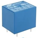
I just got a SRD-05VDC-SL-C relay, but instead of buying one pre-soldered to screws with a flyback diode + transistor (needed as the pin itself can't deliver enough power), I bought the raw device looking like:

enter image description here

The problem is that the pins are too short to fit into a screw terminal, so I ended up soldering them directly to the input 230V. As I realized it might actually be dangerous, I finally ended up buying a full relay pre-soldered to a screw terminal, but this will be quite big and might not fit into the box I wanted to use… So I'm quite curious: how safe/legal is it to sold directly a relay pin to a 230V wire? Can I test that it was properly done, e.g. by measuring its resistance? I used heat-shrink tubing to isolate them.

EDIT

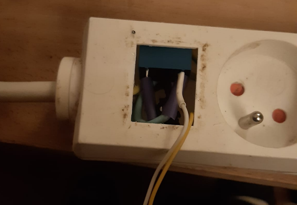
After the first answers I got, I thought it might be better to give a bit more context. My goal is to do a small DIY project (but I don't want to set fire to my flat ^^) to maintain my oven at a temperature of 25 Celsius degrees (I'm trying to make my sourdough/bread and this requires to maintain a certain temperature), by turning on/off my oven for a short period of time when the temperature drops below a given threshold. For this, my plan is to plug my oven to a power-strip that I control via an arduino, linked to a temperature sensor in the oven. I found an old broken power-strip, and I tried to solder the relay this way:

enter image description here

(note that the visible pin is not soldered as it is not used, I was planning to cover the unused pin later, but if I use the pre-soldered relay finally I'll see what to do when I'll receive it) As you can see, it fits quite nicely in this box, so my original plan was just to cover it somehow to avoid direct access to it, and connect the yellow/white wires to my arduino.

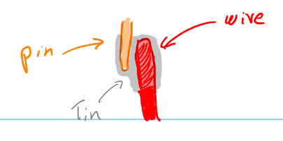
The way I soldered this was to tin the cable, place it next to the pin like this:

enter image description here

(I don't need too much mechanical resistance as it will mostly stay still in the box)

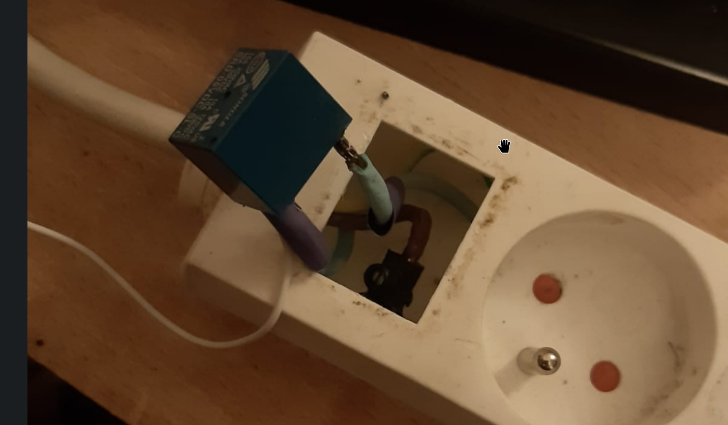
You can see this (more or less clearly, sorry for the bad picture) here:

enter image description here

You can easily see that if the relay is packed in a larger PCB, this will likely not fit nicely inside the box, so I'll need to find a way to create a safe box here.

\$\endgroup\$
2
  • \$\begingroup\$ Comments have been moved to chat; please do not continue the discussion here. Before posting a comment below this one, please review the purposes of comments. Comments that do not request clarification or suggest improvements usually belong as an answer, on Electrical Engineering Meta, or in Electrical Engineering Chat. Comments continuing discussion may be removed. \$\endgroup\$
    – Null
    Commented Nov 22 at 19:17
  • \$\begingroup\$ Dude, get a thermostatic terrarium heater! \$\endgroup\$ Commented Nov 22 at 20:52

4 Answers 4

12
\$\begingroup\$

I do not recommend this practice, but of course I've done it a dozen times. Not for production designs, just for personal projects, or quick fixes to my own equipment. I've never had issues because I took precautions.

Mounting on a PCB ensures that the relay's terminal pins are held solidly in place, and cannot bend. Since wires soldered directly to the relay terminals offer no such strain relief, if those wires can move, they can stress the relay pin where it emerges from its epoxy base, potentially breaking it off. This is a huge risk, especially if the one that breaks off is now a live wire floating freely around inside the appliance.

My solution to this was always to encapsulate and seal the pin and the first couple of millimetres of wire in an epoxy blob (not hot glue), so that the pins cannot bend, and there are no exposed metallic parts. Then zip-tie the cables to a fixed mounting point somewhere nearby (perhaps the relay itself), so the cables cannot flex near where they connect to the relay.

I say don't do this because it's dangerous. But if you do, then take precautions as I have explained. If the relay is subject to vibration, then you should never do this, period.

You should also be aware that if you cause a fire or injure somebody, there is no way that an insurance company will cover this if it is determined that your home-made appliance was to blame.

\$\endgroup\$
2
  • \$\begingroup\$ Ok, thanks a lot, I thought the issue might be related with the difference in width between the small pins and the big input wire, but good to know that what can go wrong is actually if the element mechanically move. \$\endgroup\$
    – tobiasBora
    Commented Nov 21 at 15:45
  • 2
    \$\begingroup\$ Tobais, Do as he did, not as he says for DIY. The fact that you used tin & heatshrink tells us a lot. \$\endgroup\$
    – D.A.S.
    Commented Nov 21 at 17:21
4
\$\begingroup\$

While the solder joints should be covered with shrink tube for sure, shrink tube alone sounds like somewhat questionable protection. Especially since this relay is actually intended to be used for through-hole or socket mounting.

Regarding electrical safety it is the IP ("ingress protection") standard IEC 60529 that's usually applied. Depending on application there's rules for how large holes that is allowed in the electronics enclosure. There's tougher rules depending on if you are protecting against access with hand, finger, tool or wire, where IP4X or better coverts all of it. So in your case if you mount it inside a box and fixate it mechanically, you should be good if the box is IP4X or better.

On top of that, your particular application might have insulation distance specifications (clearance/creepage).

Quality of solder joints cannot be measured, it has to be done through optical inspection. A cold joint can conduct seemingly perfect for now, only to fail when exposed to cold or oxidation over time. What also matters in this case is that no sloppily peeled cable can be tolerated.

If I had to hand solder some dirty hack like this, it is tempting to twist the peeled wire around the leg for best mechanical stability, but that would make shrink tubing awkward and might jeopardize clearance distance as well. So you'd have to do some questionable joint where the wire is coming in from below at the same angle as the leg. It's still not something that a serious professional would use in a real installation.

\$\endgroup\$
3
  • \$\begingroup\$ Note: this answer was written before the edits with the assumption that the OP was doing a serious electrical engineering product and not some DIY installation. \$\endgroup\$
    – Lundin
    Commented Nov 21 at 15:17
  • \$\begingroup\$ Thanks a lot. Two questions 1) when you mean inspection via optical inspection, do you mean with my bare eyes (like is it looking smooth), or is there more serious ways to do this kind of inspection? \$\endgroup\$
    – tobiasBora
    Commented Nov 21 at 16:02
  • 1
    \$\begingroup\$ @tobiasBora Eyes, microscope or automated inspection ("AOI"). Looking at it is the serious way, anyone with soldering experience can quickly tell if the joint is good or if there are quality concerns. But often you combine that with a product test in cold temperatures -20°C or lower, which tends to expose bad soldering. \$\endgroup\$
    – Lundin
    Commented Nov 22 at 7:25
2
\$\begingroup\$

How to design without design specs!

Requirement: grid voltage soldering techniques for safety.
Satisfied: with tinned contacts before soldering and heatshrink for HiV insulation. It should be a smooth solder joint that passes a 2kg pull test. The pictures look adequate yet unfinished.
Secure the relay with a suitable adhesive to prevent solder fatigue from shock and vibration and live grid wires after the shrink has melted off from partial breaks. I love just using a dot of sub-floor PU adhesive or silicone.
Protect the wire exit with a rubber grommet and a knot on the wire inside.

Unspecified requirements:
It turns out to be a sourdough oven controller relay which has some power to heat up at some unknown rate and thermal insulation to decay down to the hysteresis threshold with one or more thermal sensors connected to the still or forced air and/or pan with a pan of water for humidity control or not.

The result could be too much hysteresis with overshoot on temperature, if the pan is sensed. Or not enough hysteresis and age the contacts at some rate like every few seconds by not managing the heat power to rise slowly and having too tight a hysteresis. Relays are often 100k to 1m mechanical contacts and 1 to 10% of this for electrical cycles.

The relay coil can be driven by a transistor switch but then needs a diode across the coil to shunt the flyback current is a small loop. EMI is possible to interfere with ADC thermistor sensing but with care synchronous operations can be chosen.

EMC will depend on good grounding and shielding such as STP wire for low interference operation. If not using STP wire, twist the wires 1/cm with a drill.

An even better solution with use a rectifed AC grid with a transistor or FET switch to regulate the heater continuously with PWM then no Arduino is needed. Just an Op Amp analog bridge with one or two thermistors with compares setpoint voltage to bridge sensed voltage, Vt to adjust a PWM clock heat duty cycle in a linear fashion with limits. A comparator has high gain and thus very low-temperature error as long as it is calibrated.

Anecdote:

When I needed a DIY environmental chamber from -40 to + 40 'C +/-2 'C I used a styrofoam picnic box and suspended a 25W soldering iron away from DUT (electronic device-under-test) with an external dimmer to set the temperature and then dry ice chips, both with a muffin fan to circulate air. Total cost $25. No Arduino required. 1 week of functional/reliability Test Report invoiced $15k.

\$\endgroup\$
1
\$\begingroup\$

I would start by choosing a relay the provides the necessary spacing between the coli pins and the switch contact pins,

Then I would solder it to a circuit board then then solder wire terminals to the board and connect the wires.

Some relays have solder terminals for the coil and quick disconnects for the contacts, that's another option.

If you really want to use a PCB mount relay without a circuit board bind the wire to the pin using a constrictor knot tided in fine tinned wire before soldering and then after cleaning the flux off reinforce the joint using epoxy glue to prevent the pin from breaking off.

\$\endgroup\$

Your Answer

By clicking “Post Your Answer”, you agree to our terms of service and acknowledge you have read our privacy policy.

Not the answer you're looking for? Browse other questions tagged or ask your own question.