5
\$\begingroup\$

Regarding the microcontroller.

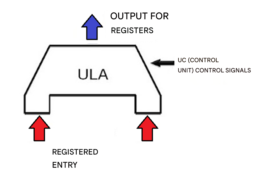
ALU - The Arithmetic Logic Unit performs all calculations involving registers and/or logic for decision making. It is connected to and controlled by the CPU in a microcontroller.

Also, the ALU is the component responsible for performing mathematical operations (addition, subtraction, etc.) and logical operations (AND, OR, NOT, etc.). In a microcontroller, the ALU is essential for data processing and instruction execution.

CU (Control Unit) Control Signals (black arrow pointing to the ALU): o The Control Unit (CU) generates control signals that determine the operation that the ALU should perform. o These signals control, for example, whether the ALU should add, subtract or perform a logical operation. o The CU decides which operations the ALU should perform based on the instructions of the program being executed.

1- I didn't understand the explanation of the CU (Control Unit). How do signals control, for example, whether the ALU should add, subtract or perform a logical operation? This doesn't make sense to me. 2- In this case, control signals determine the operation that the ALU should perform. But wouldn't the ALU itself do this?

enter image description here

\$\endgroup\$

5 Answers 5

2
\$\begingroup\$

The ALU is just a bunch of building blocks to add and subtract and stuff. Sometimes it must include the carry, sometimes it must not. Sometimes it is required to shift bits left, sometimes right. There are a lot of things it does, but it needs to be told whether to add or subtract or shift, and what features and behavioural quirks to use while it performs some function. It is given some operands, and some supplementary information like "add" or "shift", "ignore the carry" or "to the left", and does its work. It has no idea where those operands and other flags come from, or who is "listening" to the result.

All of this information is encoded in the instructions that the microprocessor is executing, but the ALU does not know how to decode those instructions. The ALU doesn't know which bit in the instruction is the "left/right" flag for a shift operation, or which instruction bit signals that carry must be ignored. It doesn't know or care where the operands and flags come from, or where to send the result once it's done.

Instructions that employ the ALU all have bits in certain places that tell the CPU what to do, such as "store the result in register A", "fetch the operand 1 from register B", "fetch operand 2 from register C", "add the operands" and "ignore the carry". Those same bits might have very different significance for different types of instructions. A branch instruction might employ those same bits in the same positions to indicate very different things, like "branch relative" and "only if carry set", but it is not the job of the ALU to interpret the contents of the instruction.

The job of interpreting instructions, determining the role of all the bytes and bits in various positions within in each instruction, is performed in part by the Control Unit. The Control Unit's role is to route (multiplex) operands from the appropriate sources (registers B and C, for example) to the ALU, provide the ancillary signals (like "add" and "ignore carry"), in a form that the ALU expects. Once the ALU has done its job and presented its results, the Control Unit then routes those results to the appropriate destination, such as register A or the data bus.

CU: tells the APU what math to do, providing the necessary data to operate upon, and flags indicating specific behavioural "tweaks", and routes the result to the appropriate destination.

ALU: does the math, unconcerned with where the data comes from or where the result goes to.

\$\endgroup\$
3
\$\begingroup\$

The function of the control signals are determined by the design of the ALU, so my answer should be considered as one possible implementation.

That being said, the simplest answer is that control signals control a multiplexer. The A and B input signals are fed into all of the building blocks of the ALU, e.g. an adder, a set of bitwise AND gates, a set of bitwise OR gates, a set of bitwise XOR gates, etc. The multiplexer selects one of those blocks' outputs and passes it through to the ALU output.

Other control signals control input multiplexers that determine which of a set of inputs are actually fed into the ALU.

One exception is performing twos-complement subtraction on a ripple-carry adder; recall that subtraction is simply adding A + B' + 1. You can accomplish a subtraction with a 'subtract' signal by bitwise-XORing B with the subtract signal, and applying it to the least significant bit's carry-in input. Then, when the subtract signal is asserted, the XOR gates complement B, and the LSB carry-in provides the extra +1.

The control unit outputs the correct control signals for the current instruction / micro-instruction, and the multiplexers in the ALU use them to select the proper output. It's all multiplexers.

\$\endgroup\$
1
  • 1
    \$\begingroup\$ +1 on mentioning a multiplexed operation that "chooses" the operation. This is exactly what I was taught when I was learning how a typical MIPS ALU worked. More information can be found here starting on Page 27 of this document. Multiplexing also appears in subtraction operations as well. \$\endgroup\$
    – Colin
    Commented Nov 21 at 21:07
3
\$\begingroup\$

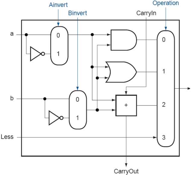
To provide more of a visualization of Matt's answer, here's a good diagram of how MIPS architecture handles their operations. This is a 1-bit ALU:

enter image description here

Picture can be found in the textbook Computer Organization and Design MIPS Edition: The Hardware/Software Interface by Patterson and Hennessy.

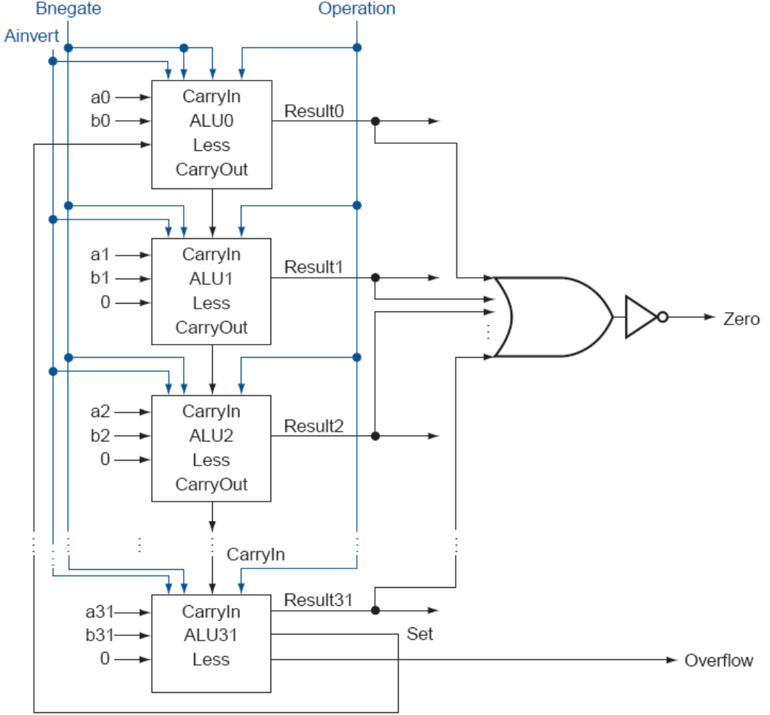
So you can see the "Operation" bit(s) that "selects" the operation that multiplexes a particular function that can be performed between "a" and "b": add, AND, OR, less than, subtract, etc. If we invert "a" or "b", as shown with "Ainvert" and "Binvert", we can perform a subtraction. There are other operations like overflow or zero detection. More operations can be accomplished, which has been proven with more modern architectures but this is simply just an example of a 32-bit MIPS ALU:

enter image description here Picture from the same source as mentioned above.

So basically in order to get a result from two numbers, you are first choose an operation, e.g. 0x02 for addition shown here, then the binary numbers for "a" and "b", e.g. a[0:31] = 111010...001 and b[0:31] = 101010...010, and then it will output the result, e.g. 010 (for add) 111010...001 (a), 101010...010 (b) --> (1)010100...011 stored in memory but oh wait, there's an overflow with the extra (1)... Raise that flag This is pretty much how your Assembly works.

\$\endgroup\$
0
\$\begingroup\$

The ALU can take two numbers in, do some operation to the two numbers, and output the result. It can do any one operation out of many available but it must know which operation to do. The information which operation to perform comes from the control unit.

So the ALU just does the operation that it is told to perform. The control unit can't do anything with the numbers itself but it knows which operation should be performed on the two numbers and sends that information to the ALU so the ALU can choose to do the correct operation.

\$\endgroup\$
0
\$\begingroup\$

I didn't understand the explanation of the CU (Control Unit). How do signals control, for example, whether the ALU should add, subtract or perform a logical operation

It's the same as in a simple calculator. The human operator is the source of control inputs.

In an ALU, the instruction stream provides the control inputs, via the instruction decoder.

The calculators - or ALUs - can be designed in many different ways. The exact way this behavior is achieved can vary a lot. For example, a calculator may have a microcontroller, so choosing the operation based on control inputs from the keypad is done in software.

control signals determine the operation that the ALU should perform. But wouldn't the ALU itself do this?
The ALU is a calculator. It doesn't decide what to do by itself, it wouldn't be very useful then.

Sure, there are single-function calculators and they are very useful - e.g. the adder within an ALU, or a mechanical cash register adding machines - but we don't call them ALUs. We call them ADDERS.


When making homebrew computers out of easily available digital chips, the simplest ALU is often a bunch of memory chips. They take e.g. a 16 bit address in, and output an 8 bit output. Paralleling the RAMs or EPROMs lets you have wider output, and more than just one function.

The memory is loaded with a table of values of the function it is to perform. So you can think of there being two sets of control inputs, disjoint in time:

  1. The initial table load into RAM or EPROM, which determines the exact operation performed (e.g. addition, squaring, reciprocal, etc.)

  2. The subsequent selection of output from just one function's RAM chips. That determines which of the preloaded tables is used in the calculation.

It used to be that memory chips were very expensive - that's not really the case nowadays. So, it is a feasible approach for homebrew computers, but was not really possible in consumer computers back in the 80s-90s.

Memory is, in a way, just a programmable arbitrary logical function generator. So, taking this approach to conclusion, you can build an entire computer out of memory and a couple of latches. One example is THE GRAY-1, A HOMEBREW CPU EXCLUSIVELY COMPOSED OF MEMORY (pdf).

\$\endgroup\$

Your Answer

By clicking “Post Your Answer”, you agree to our terms of service and acknowledge you have read our privacy policy.

Not the answer you're looking for? Browse other questions tagged or ask your own question.