I am currently designing a FOC motor driver with a MCF8316C chip from TI and I am having quite a lot of troubles to get it to work. I plan on controlling it with a PWM signal coming from a Nucleo-f429zi board from stmicroelectronics.
The chip default setting is for it to work with analog input. It is possible to change that by changing the register with I²C commands. However, I understood from the TI Forum that the protocol of the device is flawed (unusual ID, needs delay between each byte package or to set the speed to 10 kHz instead of 100kHz). I’ve done all that but the driver just won’t work I am relatively new to coding so I am a bit lost.
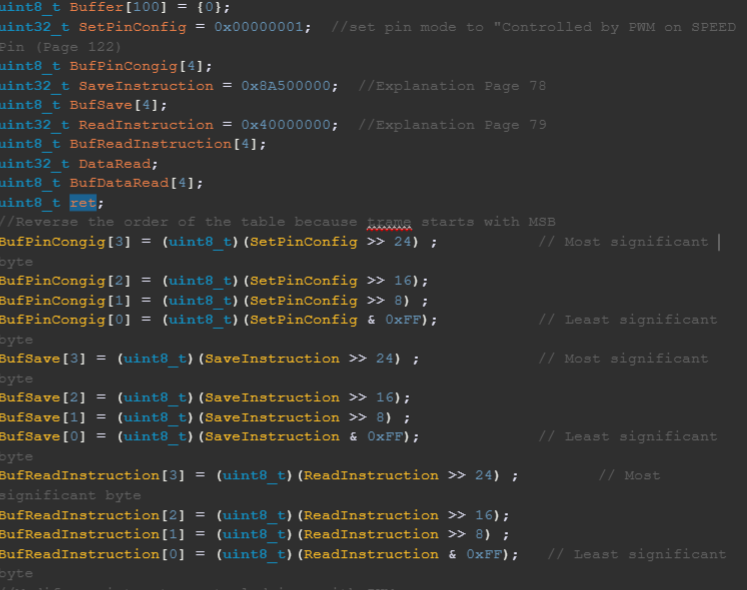
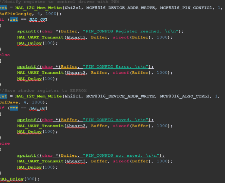
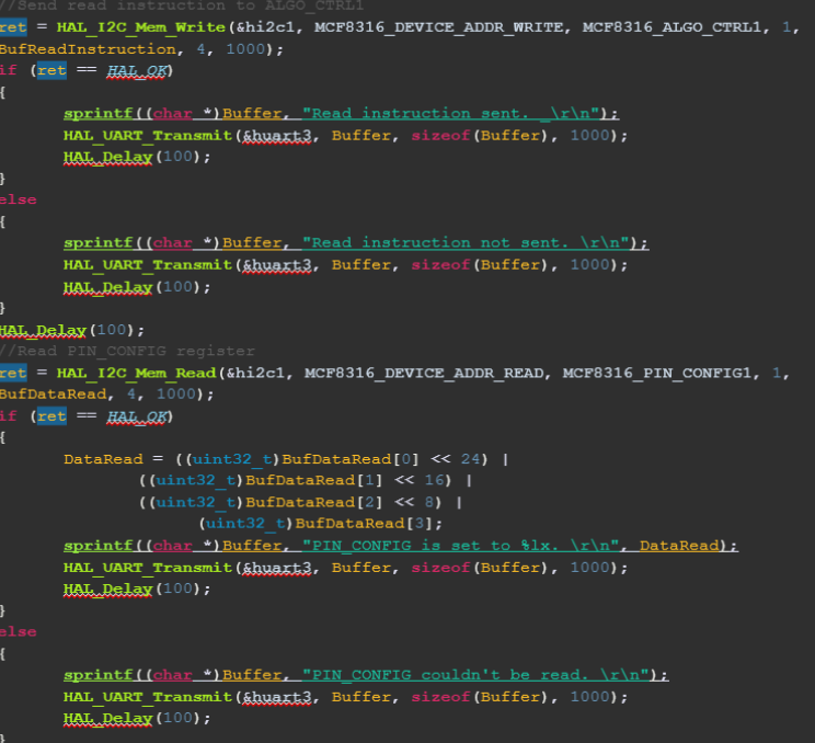
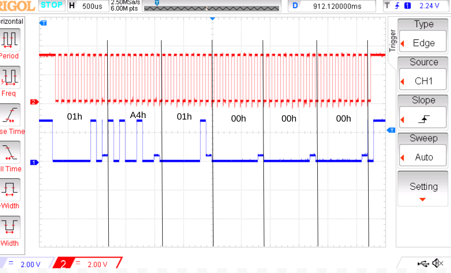
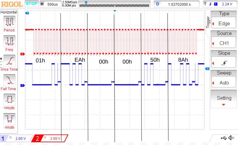
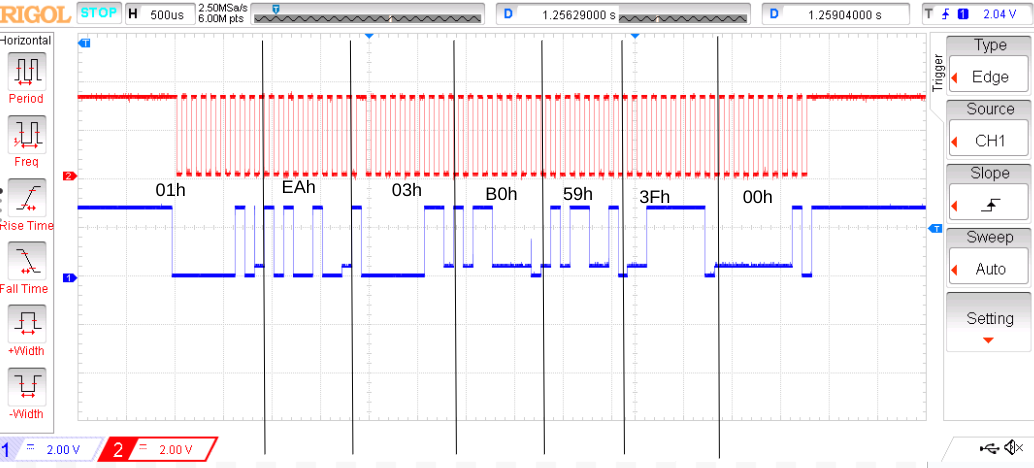
So far I’ve sent the config that i want to the register, then sent the command to save the config in the shadow register to the eeprom, then tried to read the changed register but the output doesn’t make sense. Instead of having 0x00000001, I have 0x003f59b0. Since the default setting is 0x00000000 and I haven’t changed anything else I don’t understant why I have this. I looked at the frame sent and I don’t see anything wrong.
Here is the code I am using:
''' Code '''
Here is the link of the datasheet : https://www.ti.com/lit/ds/symlink/mcf8316c-q1.pdf
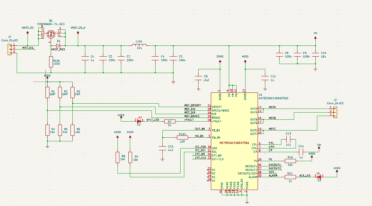
Here is the schematic of the board with the driver
The code I am using :
And here are graphs of the data sent and received
Someone has any idea on what I am doing wrong?

{}on a new line, and past your code). \$\endgroup\$MCP8316_DEVICE_ADDR_WRITEvalue? The datasheet said "Target ID and R/W Bit: The first byte includes the 7-bit I2C target ID, followed by the read/write command bit" (i.e. shift A6-A0 up by one bit and add 0 as the Lowest bit for WRITE operation). so if Target I2C ID is 0x01, theMCP8316_DEVICE_ADDR_WRITEshould be0x02. But your scrope shows that you are sending0x01. \$\endgroup\$