3
\$\begingroup\$

I currently have a circuit that controls the state of a relay. The relay is driven by an NMOS transistor M1, and the gate of the NMOS is driven by a microcontroller. Additionally, I have an LED indicating the state of the relay, and this LED is also controlled by an NMOS M2. The circuit looks like this: -
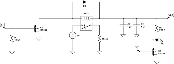
schematic

simulate this circuit – Schematic created using CircuitLab

The gate of both NMOS are driven by the same microcontroller pin, so they turn on and off synchronously. When D1 is HIGH, the relay is conducting and the LED is on.

I want to get rid of M2 but I still want an LED to show the state of the relay - but I don't want to drive the LED directly from the microcontroller pin. The LED should be supplied by \$V_\text{DD}\$. The NMOS device is allowed to be changed into a PMOS transistor. Would something like this work? Or is there another approach that is more reasonable.
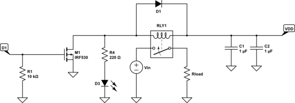
schematic

simulate this circuit

Edit

I now realize that my suggestion will obviously not work, because M1 drives the anode of the LED to 0 volts when on, and the cathode is also connected to ground - hence no current flow.

\$\endgroup\$
2
  • 2
    \$\begingroup\$ Just power the LED and resistor with Vdo ... and the low pin of LED wired to drain M1. \$\endgroup\$
    – Antonio51
    Commented Dec 2 at 8:57
  • \$\begingroup\$ You may need a series resistor to the gate of M1 to prevent high-frequency oscillation, since you are driving an inductor. See Section 3 of toshiba.semicon-storage.com/info/… \$\endgroup\$ Commented Dec 3 at 2:46

4 Answers 4

10
\$\begingroup\$

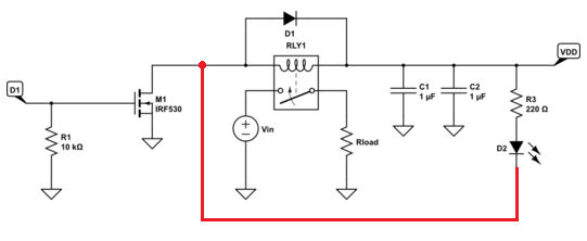
Why not try connecting the LED like this: -

enter image description here

I've taken you first schematic and added a wire in red.

\$\endgroup\$
3
\$\begingroup\$

It will/might** work, but the polarity is now reversed : the LED will now be on when the relay is off, and off when the relay is on.

If D1 is high, then M1 will act as an short circuit, so the node between relay and R4 will be at ground potential, so no current will flow through D3. The coil of the relay is energized

If D1 is low, M1 is open circuit. A (small**) current will still flow through the relay coil, R4 and D3 : D3 will be on. There is a small current through the relay, but hopefully small enough that it doesn't turn on.

** Note that the value of R4 needs to be carefully : if R4 is too small, the current through the relay will be too big when M1 is off, and the relay will never turn off (nb : check carefully the datasheet of the relay for the guaranteed release current, which s usually far smaller than the turn on current). If R4 is too big, then your LED will be very dim.

An alternative might be to place D3 (and maybe a resistor) in series with the relay coil. You will have the same current through the coil and the LED. But this means you need a LED that can handle the coil current. And you have to check if you still need a current limiting resistor, and if so, make sure you still get enough current to turn on the relay

\$\endgroup\$
3
\$\begingroup\$

In the second schematic in the question, when the MOSFETs are off, current will flow through the relay coil and light the LED. When the MOSFET is on, the LED will be shorted. So the LED will be inverted relative to the relay.

Two snippets from my schematics:

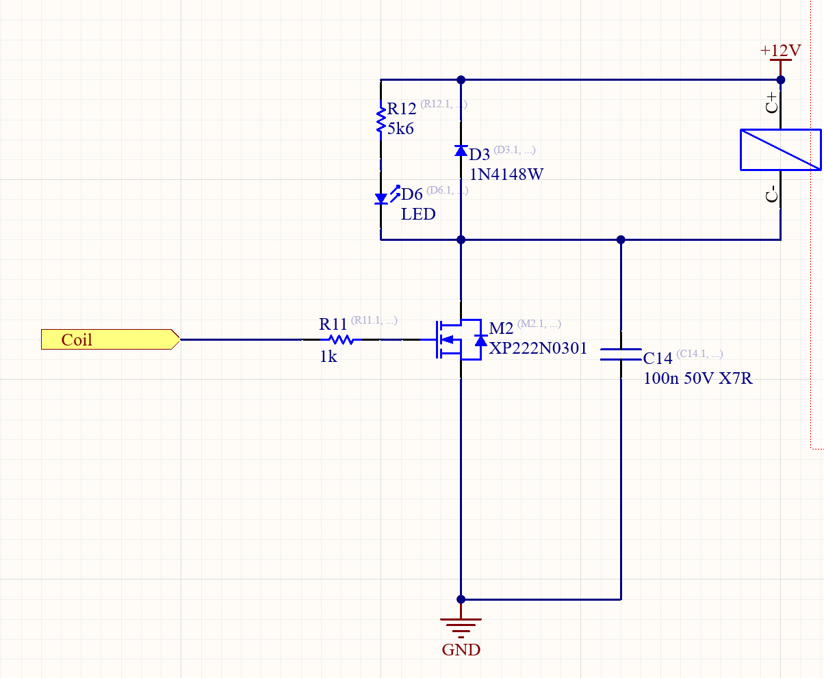
  1. Wire the LED and resistor in parallel with the relay coil. When the coil is energized, the LED will turn on.

enter image description here

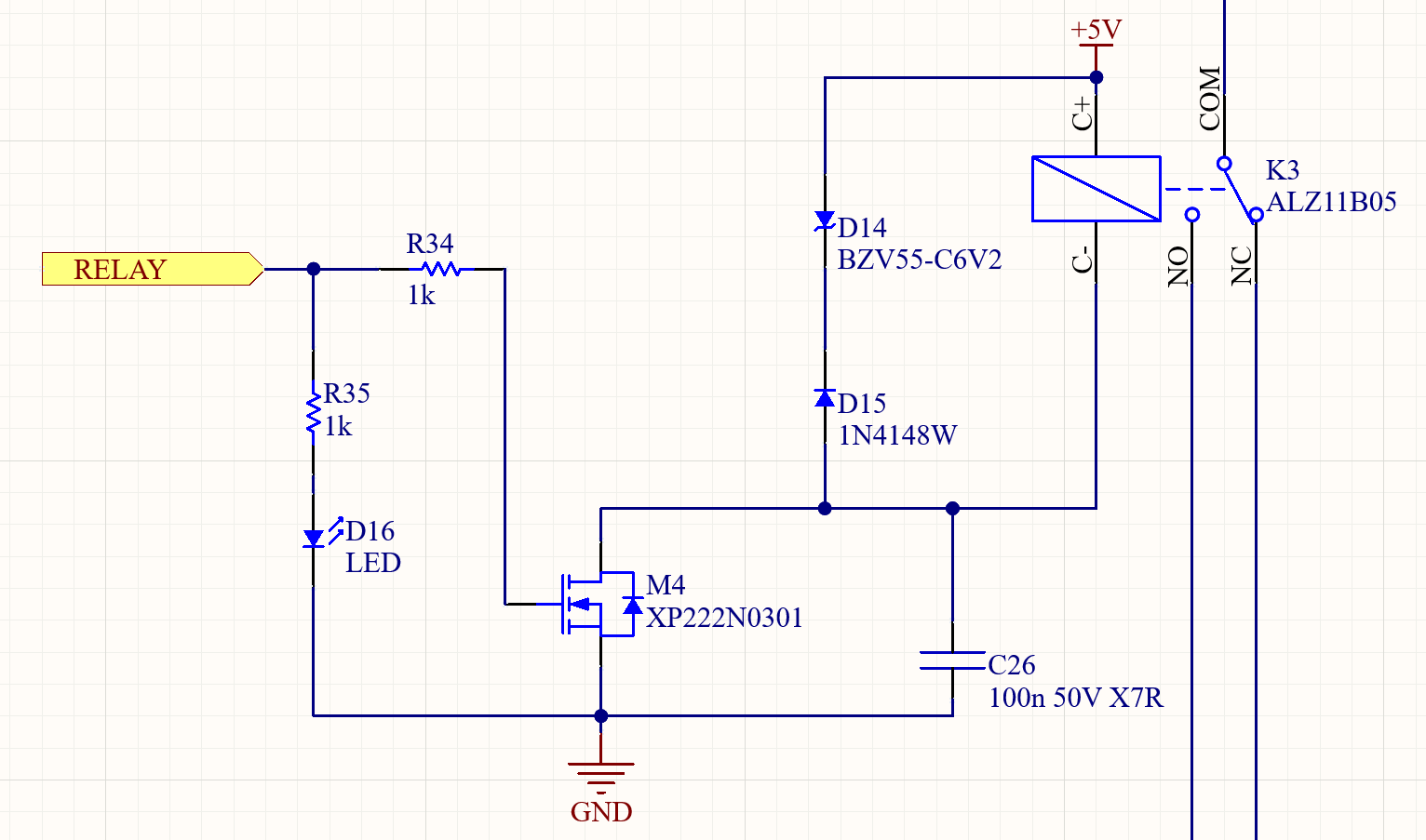
  1. Wire the LED on the MOSFET gate. In this case I needed the relay to turn off quickly, so I added a Zener diode in series with the usual freewheeling diode to dissipate the magnetic energy quicker. This means when the MOSFET turns off, there will be more than 5V reverse voltage on the relay, which is more than a LED can tolerate. Thus I put the LED on the input side.

enter image description here

In another circuit I had 16x 24V relays, that's a lot of LEDs. In this case it was a bit more efficient to drive them from 3V3, which came from a switching converter, than to drop 24V with a resistor.

The deciding factor could also be convenience: if the LEDs need to be close to the micro, say on a front panel, then it makes sense to put them on the MOSFET gate side.

\$\endgroup\$
2
  • \$\begingroup\$ One concern with the first circuit: there is no resistor from M2's gate to ground. If the microcontroller pin is not configured as an outputs (including at reset), given any leakage current the MOSFET gate could drift high and put it into high-dissipation linear operation. \$\endgroup\$ Commented Dec 3 at 2:56
  • \$\begingroup\$ That's true. I realized the pulldown resistors are on the MCU schematic sheet after copypasting \$\endgroup\$
    – bobflux
    Commented Dec 3 at 9:32
0
\$\begingroup\$

A different approach I've used a few times: Use spare terminals on the relay to control the LED.

I often use the TQ2-5VDC relay because it's suitable for a lot of what I do, but I don't always need both sets of contacts. The spare set can be used between any convenient voltage rail and ground, with an LED and resistor, to indicate the state of the relay.

An advantage that's not so applicable here: when your relay isn't hard-wired to a digital drive, and is subject to analogue or human failure modes such as powering the coil through pogo pins when an accessory is attached to a primary fixture.

\$\endgroup\$
1
  • \$\begingroup\$ One consideration is the type of relay contacts. Small signal contacts will keep working; power contacts -- which count on a bit of an arc to keep them clean of oxidation -- will eventually give you problems. \$\endgroup\$ Commented Dec 7 at 19:02

Your Answer

By clicking “Post Your Answer”, you agree to our terms of service and acknowledge you have read our privacy policy.

Not the answer you're looking for? Browse other questions tagged or ask your own question.