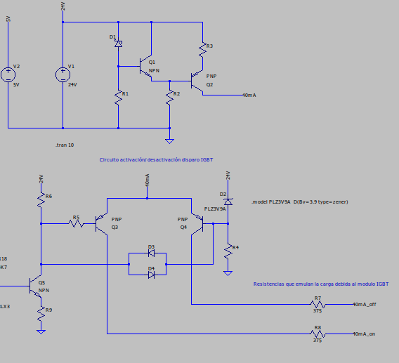
I am trying to understand how the circuit in the image works. I have managed to understand how the 40mA constant current source works, but I cannot understand how it performs the switching between transistors Q3 and Q4. Could someone give me a clue or an explanation of how the calculations for this switching circuit are? Q5 works in cut-off/saturation, depending on its state Q3 or Q4 must conduct. Thank you very much.
LTspice simulation based on the block diagram [here] https://i.sstatic.net/M6LQJ1lp.jpg of the manual: https://es.scribd.com/document/674848740/4C-Device-Manual-Sibas
I think I've solved it, here is the solution I found: In R4 we have 21.1V that the zener sets, if Q5 does not conduct, in R6 we have 24-21.1-0.6=2.3V. We must calculate R4 and R6 so that the current flows through D4 and is enough for the zener to maintain 3.9V. In this way, Q4 conducts, so that it conducts the constant current source must provide at least 21.7V, polarizing with 0.6V base-emitter. On the other hand, in the base of Q3 there is 21.7V, the same voltage as in the emitter, so it does not conduct.
When Q5 conducts in R9 we have the base voltage (5V) - 0.6 = 4.4V, if we now calculate a value for R9 such that the current flows through D3 the voltage at the node between R4 and D3 will now be 20.5V, so Q3 will conduct and the constant current source will decrease the voltage to 21.1V so Q4 stops conducting. I hope I have explained myself correctly and thank you all very much.

