6
\$\begingroup\$

We're trying to build a circuit that switches on a pump via a Pi gpio pin.

Requirements

  • Pump: runs at 5V, working current ca 100 mA (Link)
  • PI gpio pin restrictions apply: 3.3V, max allowed draw is low (Ref)
  • Runtime via "high": Pump needs to run as long as gpio is "high", normally 1-3 seconds
  • Maximum runtime: Pump must never be allowed to run more than approx. 5 seconds, even if the gpio stays high longer (failsafe)
  • Cooldown: Can not immediately "re-start" pump, desired cooldown is around 30 seconds (failsafe)

Solution Attempts

I've come up with multiple ideas, but they all have some (major?) problems

1. Mosfet

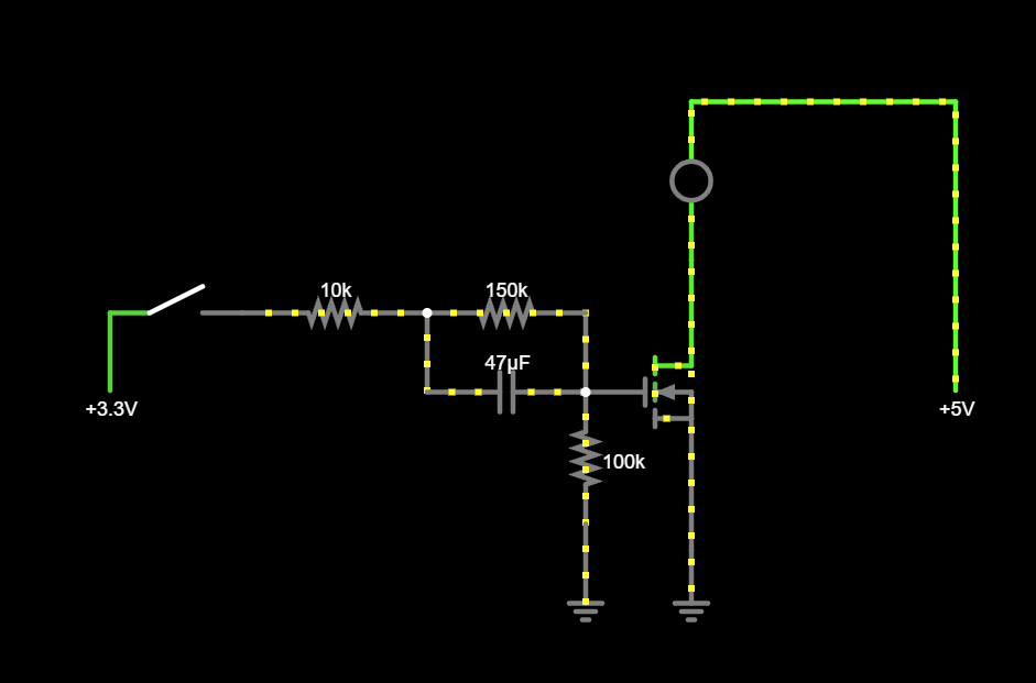
Using a simple Mosfet Irf510.

This works, but does cause the Mosfet Gate Voltage to change slowly. And my understanding is that Mosfets don't like being in the Miller Plateau for very long (lifespan!). Then again, the Mosfet is extremely beefy and this is only in the emergency phase - i.e. shouldn't happen very often. So maybe this is not a problem?

Related to that, the auto "shutoff" isn't abrupt, but gradual. This is undesired.

Click here for simulation

Mosfet

2. 555 with Mosfet

Using a 555 timer IC. There are some problems with this

  • Inductive Load of the pump would probably destroy the 555
  • Voltage at Source and Drain for the Mosfet would probably reduce lifespan
  • Even if this was salvageable, there are lots of components used (!)

Click here for simulation

555

3. Microcontroller

Using a MCU, e.g. a STM8S103.

I haven't actually tried this. It should work, but seems somewhat overkill - especially since it would require flashing custom firmware.

Question

Do you see my attempts (1) or (2) being salvageable? I really like (1), but I have some major concerns wrt lifespan. Any different components / circuits that I should look into? Maybe a Zener Diode? Or is the MCU my best option?


Note: I'm new to electronics and circuit board design.

New contributor
vincent is a new contributor to this site. Take care in asking for clarification, commenting, and answering. Check out our Code of Conduct.
\$\endgroup\$
5
  • 1
    \$\begingroup\$ (MOSFET is an acronym.) \$\endgroup\$
    – greybeard
    Commented Dec 6 at 5:58
  • 1
    \$\begingroup\$ Why not get to the heart of the matter and measure pump temperature to decide whether it can be activated. \$\endgroup\$
    – Andy aka
    Commented Dec 6 at 10:42
  • \$\begingroup\$ why don't you program your RPi to turn off the pump after a defined time, and implement the safety via a watchdog timer? \$\endgroup\$ Commented Dec 6 at 13:10
  • \$\begingroup\$ Independent of the actual motor driver, is there a reason you cannot implement the runtime and cooltime restrictions and logic in Pi firmware? \$\endgroup\$
    – AnalogKid
    Commented Dec 6 at 20:27
  • \$\begingroup\$ you can get a timer relay module for dirt cheap with several tunable options, including turning on from signal and off after 5 seconds, ignoring the signal until it goes low then high again. \$\endgroup\$
    – dandavis
    Commented Dec 6 at 20:27

3 Answers 3

6
\$\begingroup\$

The MCU option is overkill only once; you acquire the programming equipment and software, and you acquire the knowledge to use them, and then you have that for life. In addition, you have a single 8-pin IC solution (plus a MOSFET to switch the pump), in contrast to an analogue solution using discrete parts, which is necessarily more complex. If that's not enough to convince you, then consider that firmware is easier to change than a chunk of a circuit or entire PCB.

The simulation of your first circuit uses a closed switch to emulate the presence of a +3.3V input, but an open switch does not correctly represent the 0V that a GPIO output would present there. You should use a changing voltage source to emulate GPIO potential, or at least a double pole switch which flips between ground (0V) and +3.3V.

The reason for your first circuit's failure, and sluggish behaviour, is that the transistor's gain is insufficient to respond to slow-slewing gate potentials with an emphatic on or off state. You'll require another transistor to boost gain. The IRF510's \$V_{GS(TH)}\$ can be as high as 4V, which means there's a very good chance that a 3.3V signal will be insufficient to switch it on. You'll definitely require level translation (another transistor), or a transistor with lower \$V_{GS(TH)}\$. The idea could be salvaged with more transistors, but its simplicity is then lost.

The 555 timer may be able to source 100mA of current from its output, but the pump motor will no doubt require significantly more while it accelerates from stop. Therefore you should still employ a transistor to do the heavy lifting, rather than relying on the timer IC. If your 555 design does what you want, except for the load issues, then just add another MOSFET or BJT to offload that responsibility, and also to isolate the 555 from the load somewhat. Don't forget the free-wheeling diode D1 to protect M1 from the inductive load:

schematic

simulate this circuit – Schematic created using CircuitLab

\$\endgroup\$
2
  • \$\begingroup\$ If you can't control timings in "PI pin" to meet your requirements, Simon's answer is perfect. Additionally, consider, as part of your training, building your own device to write firmware to a MCU. A PIC12F675 is more than enough for your purpose. I developed a low cost PIC recorder project (github.com/NelsonBittencourt/PicArd) that might be useful. \$\endgroup\$
    – Nelson
    Commented Dec 6 at 14:06
  • \$\begingroup\$ I agree that a small microcontroller is perfect for this. I needed a watchdog circuit for a higher level MCU and couldn't find a dedicated IC with exactly what I needed. Ended up using an 8-pin PIC10F320 with a very simple program. MPLAB software was free and the programmer was inexpensive. Worked great. \$\endgroup\$
    – kolyur
    Commented Dec 6 at 14:23
1
\$\begingroup\$

When using low-power electronics to control anything with a motor in it, I frequently find that it's a lot easier to use a relay instead of a transistor. The on/off transitions are just as sharp as flipping a mechanical switch. You can isolate your electronics from the pump/motor so there's no longer any concern about running at different voltage levels, how much current your microcontroller can supply from a GPIO pin, whether the motor's inertia induces a current once you switch it off, etc.

Given your requirements, you could use a 555 timer in monostable/one-shot mode to generate a pulse that was 5 seconds long. AND the output of the timer with your GPIO line, then use that to control the relay. The relay will turn on when the GPIO goes high, and it will turn off when either the GPIO line or the timer's pulse go low.

If you want your 30-second cooldown period to also be enforced by hardware, you could use a 556 timer IC (two 555s in one chip) instead. Set up the second timer as a 30 second one-shot timer, and trigger it with the falling edge of the 5-second timer. The output signal controlling your relay would then be (GPIO AND short timer AND (NOT long timer)).

\$\endgroup\$
0
\$\begingroup\$
  1. Independent of the actual motor driver, is there a reason you cannot implement the runtime and cooltime restrictions and logic in Pi firmware?

  2. Circuit #1 certainly is salvageable. The only real problem with it is that the resistors form a voltage divider of almost 3:1. With the circuit as shown, the max steady-state gate voltage is only 1.27 V. That's not enough for most "normal" MOSFETS.

You don't say how slowly the MOSFET gate voltage is changing. Anything under 1 second should be OK, and anything under 100 ms is fine. In your schematic, you can eliminate all of the R's and C's, and drive the gate directly with anything up to 20 V (for most MOSFETS). If you have room, just about any power MOSFET in a TO-220 package will run almost forever without a heatsink. Because of the relatively low gate voltage, be sure to select a "logic level" n-channel MOSFET.

  1. An inductive load will not "destroy" a 555 output. A single diode across the motor will protect the chip. Note that only a bipolar 555 can supply the required current, but there will be a significant voltage loss in the 555 output stage. The motor might see only 3.5 V.
\$\endgroup\$

Your Answer

By clicking “Post Your Answer”, you agree to our terms of service and acknowledge you have read our privacy policy.

Not the answer you're looking for? Browse other questions tagged or ask your own question.