0
\$\begingroup\$

I made a buck converter using MP2315s, and when I tested the final product it didn't work like it should be dropping 12v to 5v. Tested and no output

I input a 12v to the input of the PCB, and the input capacitors and the diode worked fine, it shows a 12v rating on my multimeter.(there were some electrical sparks when I was testing it using the multimeter i don't know if this caused the issue)

I tested all my components to see if they were damaged or burned out but none of them were.

All shows 0v after the input capacitors

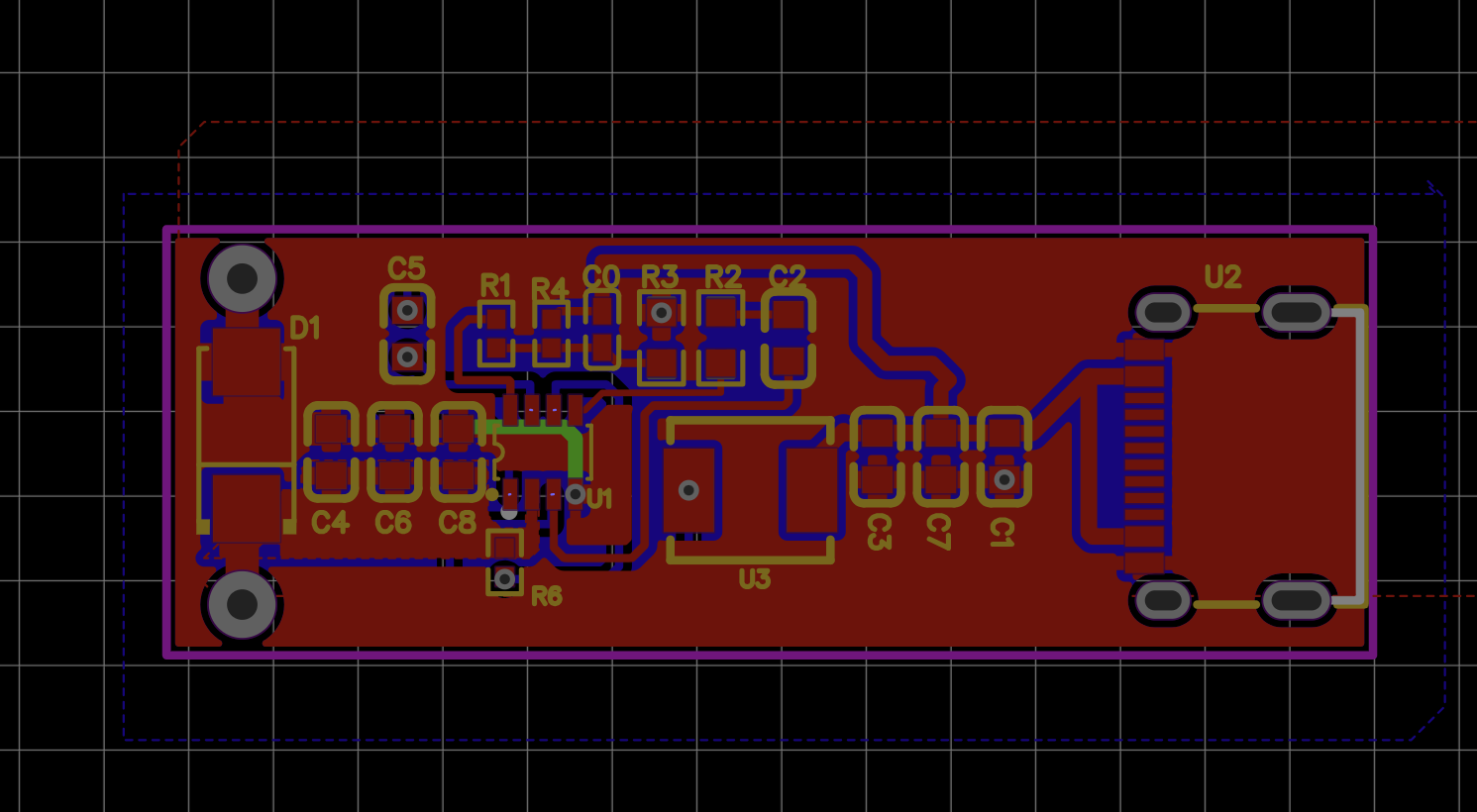
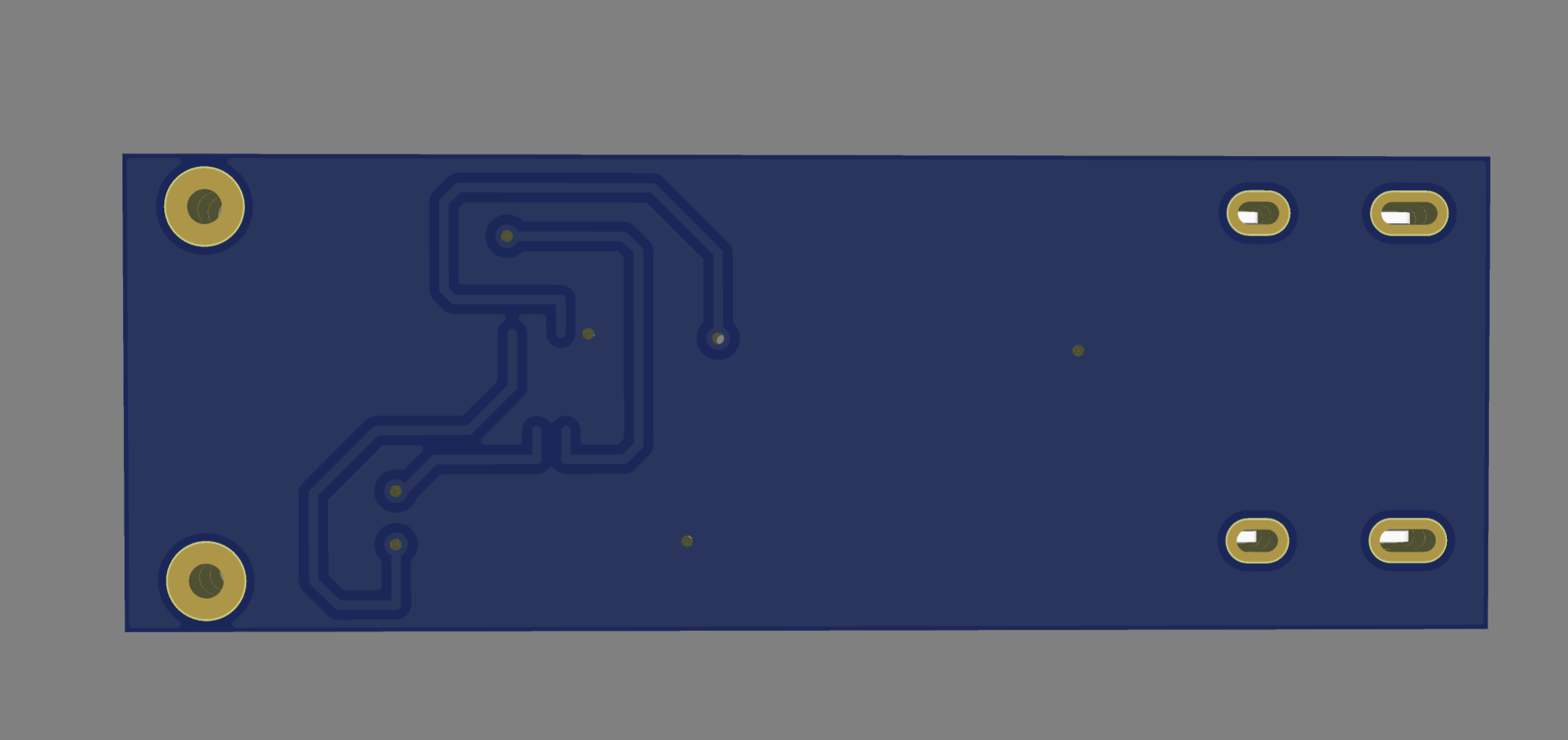
Does anyone know what's the issue here?(maybe it's my layout problem?)

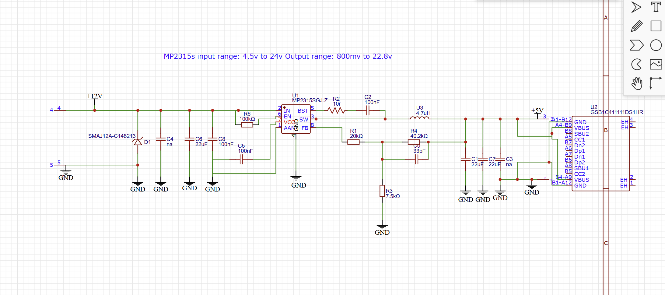
Schematic: Schematic

PCB layout:enter image description hereenter image description hereenter image description hereenter image description here (Ignore that the inductor is missing on here)

I didn't solder the Type C on when measuring.

(Sorry if this looks horrible, I'm new to this, and just wanna try it out)

MP2315s datasheet: https://www.monolithicpower.com/en/documentview/productdocument/index/version/2/document_type/Datasheet/lang/en/sku/MP2315S/?srsltid=AfmBOopWgiG3ZEwPZFbEzq1Ndjh2yn8yPgv9rgeM2hVrG93F_E1sUOeh

New contributor
fish is a new contributor to this site. Take care in asking for clarification, commenting, and answering. Check out our Code of Conduct.
\$\endgroup\$

1 Answer 1

0
\$\begingroup\$

From the first look of your schematic and datasheet, I think you configured AAM wrong by connecting to GND. The datasheet mentioned either leave the pin floating, connect to VCC or connect to a resistor network enter image description here

Figure 6 in the datasheet also mentioned the suggested AAM voltage for different output voltage and inductor.

\$\endgroup\$

Your Answer

By clicking “Post Your Answer”, you agree to our terms of service and acknowledge you have read our privacy policy.

Not the answer you're looking for? Browse other questions tagged or ask your own question.