2
\$\begingroup\$

I need to communicate a microcontroller (Btm, Arduino Uno) that it reads 3.3 V as (1) and 0 V as (0), with another microcontroller (Top, Arduino Uno) that reads voltage 3.3 V as (0) and 6.6V as (1) and it is the same for its output voltage. In order for them to communicate with each other, I need to increase microcontroller (Btm) logic (1) voltage from 3.3 V to 6.6 V, vice versa from 6.6 V to 3.3 V for microcontroller (Top) logic (1). For their low voltage I could use voltage divider from Top to Btm and there should be no problem for low logic to communication from Btm to Top.

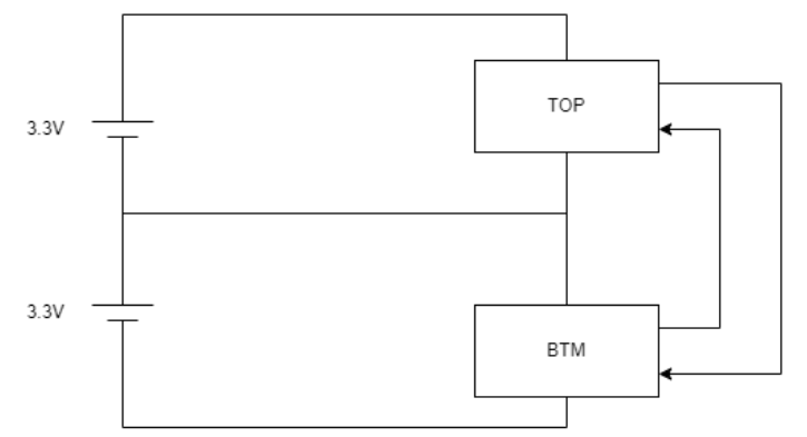
The Power Supply is DC supply, and currently I am focusing on the correct communication of High and Low logic between both microcontrollers. I am attempting voltage stacking with microcontrollers to see the effects of it but the data communication issue was observed as a effect.

My question is what kind of circuit should I build so that I can achieve this?


I had stacked MCUs together. The arrangement looks something similar to diagram below, I had trouble for them to communicate with each other. As the microcontroller (Top) output will be read as high regardless logic 0 or 1, and microcontroller (Btm) output will be read as low regardless logic 0 or 1.

enter image description here

New contributor
Samuel Cheng is a new contributor to this site. Take care in asking for clarification, commenting, and answering. Check out our Code of Conduct.
\$\endgroup\$
9
  • \$\begingroup\$ What power? Just signals or high load? What frequency? Continuous (analog) from 3v3 to 6v6, or discrete with 3v3 and 6v6 output only? \$\endgroup\$ Commented yesterday
  • 1
    \$\begingroup\$ This question can be reopened with a little work. Please remove the question about a specific part and ask how you would construct something that does what you want. You will need to provide more detail about what you are actually trying to do. At the moment there are too many possible answers because the question is too broad. It will be easy to provide a solution once we know what the actual requirement is. Once Dan flag it for reopening. You can also tag me if needed. \$\endgroup\$
    – Russell McMahon
    Commented yesterday
  • 1
    \$\begingroup\$ Can you explain why you have Microcontrollers which don't share the same 0V and positive supply rails? I don't think people will want to answer this question, when the obvious solution is to have them share the same supply rails, and level-translate their sensor/button/analogue inputs instead. Your setup here is highly irregular. \$\endgroup\$ Commented 6 hours ago
  • 1
    \$\begingroup\$ for now let's assume arduino gpio output That's not enough information. What is the maximum frequency this output should change? What is the maximum delay allowed through the channel? Does it need to change direction, or can it work in a fixed direction only? Help us help out. Basic specs. It's just the basics. \$\endgroup\$ Commented 6 hours ago
  • 1
    \$\begingroup\$ I am attempting voltage stacking on microcontrollers and see the effect of it There are no effects. The microcontrollers don't care about absolute voltages, only about voltages relative to their own 0V pin. They don't know about anything else. How could they? \$\endgroup\$ Commented 6 hours ago

3 Answers 3

1
\$\begingroup\$

Voltage Source Offset

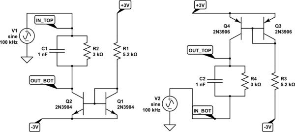
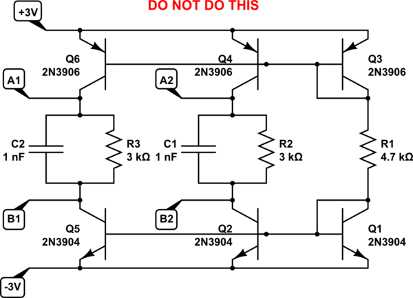
The following two circuits add a 3V "floating battery" (1mA flowing through R2, R4) between the top and bottom nodes.

The circuit on the left passes signals from top MCU to bottom MCU. The circuit on the right passes signals from bottom MCU to top MCU.

schematic

simulate this circuit – Schematic created using CircuitLab

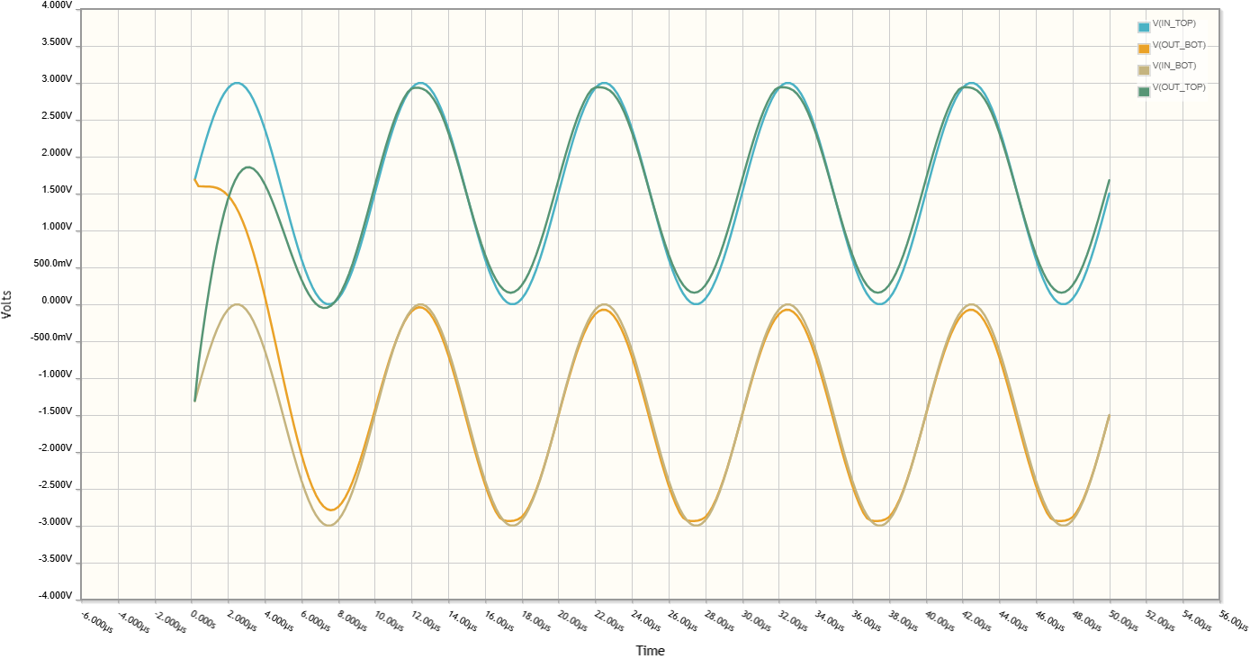
The plot of 5 cycles of a 100kHz square wave passing through the left and right circuits.

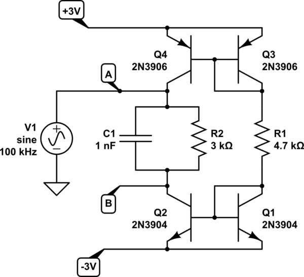
It's also possible to have a bidirectional circuit:

schematic

simulate this circuit

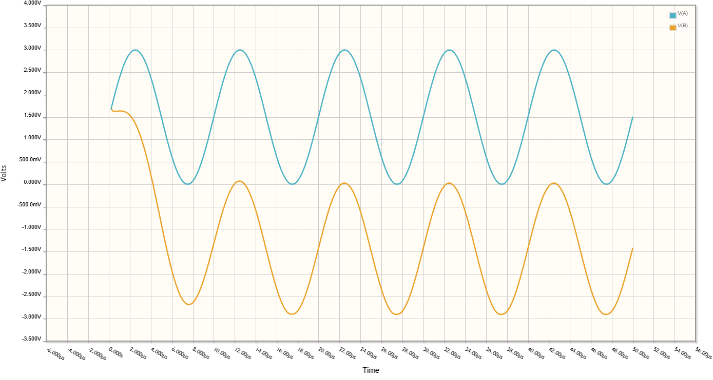
The plot of a signal passing from top to down in the bidirectional circuit

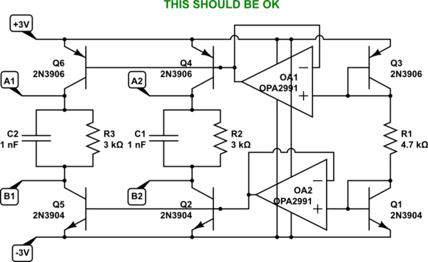
You'll need one such circuit per signal. Do not share the reference transistor outputs unless they are buffered by an opamp. For example:

schematic

simulate this circuit

The reference levels have to be buffered:

schematic

simulate this circuit

Current Switcher

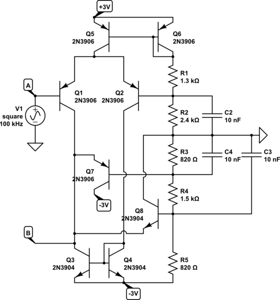
This one is quite a bit faster since nothing saturates. Q1 and Q2 direct the current from Q5 through one of the two branches, based on the logic state at A. Either Q1 or Q3 is active, and they steer B to follow A. Q7 and Q8 provide voltage clamping on B, establishing a valid output range and preventing saturation of Q3.

schematic

simulate this circuit

That circuit has input on the top, output on the bottom. For the other direction, mirror the schematic along the horizontal axis, and swap transistor polarity (PNPs with NPNs).

\$\endgroup\$
1
\$\begingroup\$

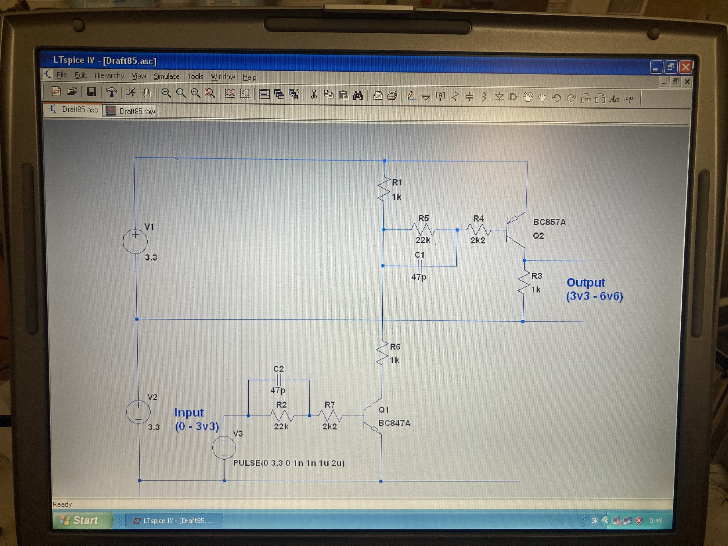
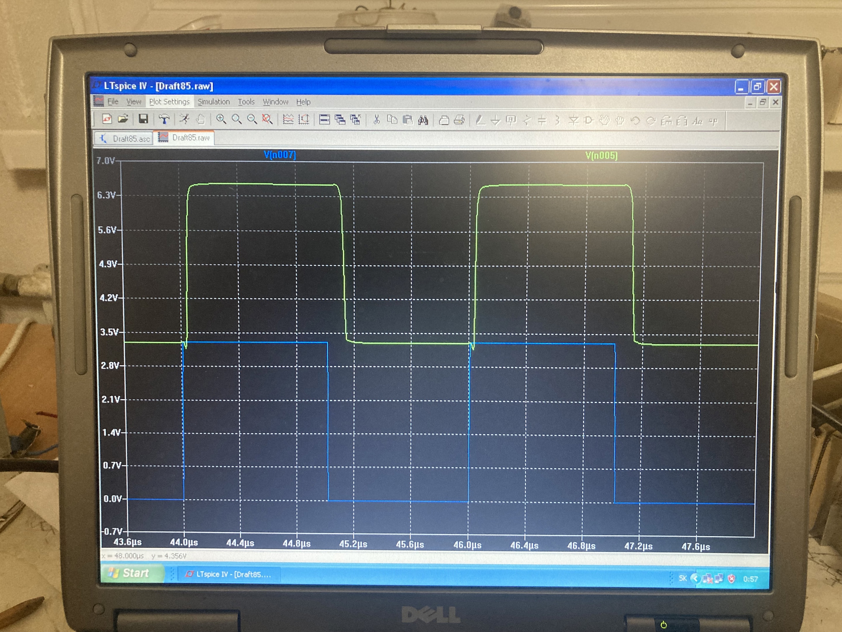
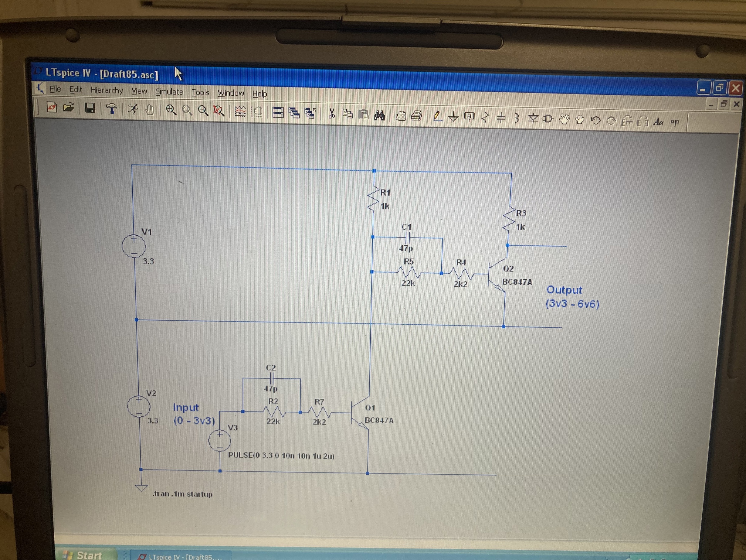
This simple solution isn’t sufficient? Even with “slow” BC847 & 857 it can be used up to 500kHz.

enter image description here

500kHz input signal:
(Blue is input, green is output)

enter image description here

Edit:

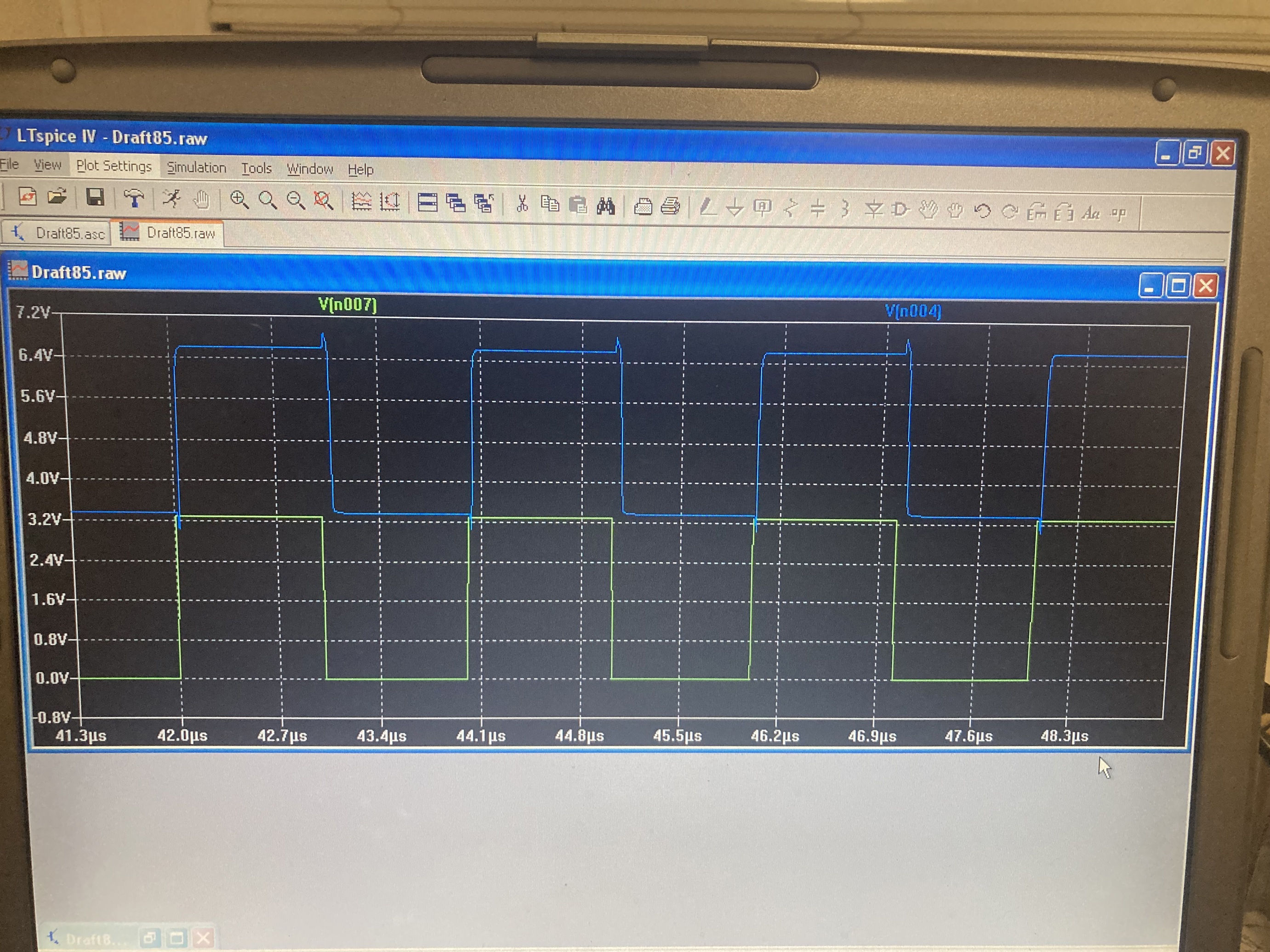
There is an option to use a two NPN inverter. The output pulse will be more symmetric and the overall delay will be splitted to both edges, so half of delay will contain rising edge and half falling:

enter image description here

enter image description here

\$\endgroup\$
0
\$\begingroup\$

enter image description here

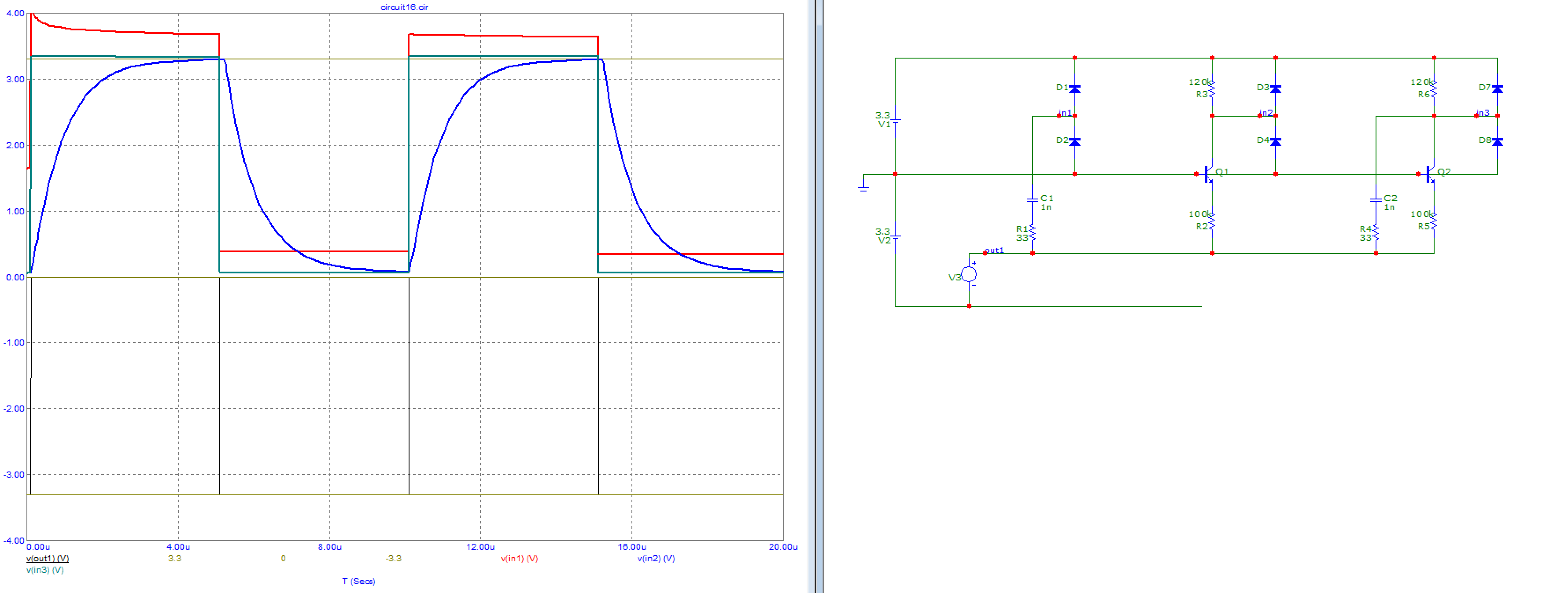
Bottom MCU output is voltage source V3. Top MCU inputs are nodes in1...in3. Diodes shown are the MCU's input protection diodes, could also be added as BAT54S for example.

On the left: capacitive coupling. Cheap and fast, but does not pass DC. Input protection diodes take care of holding the voltage more or less in the right window.

Middle: using a transistor as common base stage to do the voltage translation. Cheap and slow, passes DC. Simulated with the ubiquitous MMBT3904. Power consumption is proportional to speed, because higher value resistors will give slower rise/fall times. I adjusted resistor values to avoid saturation in the BJT. The top resistor has a little higher value to compensate for Vbe drop on the bottom resistor. It would also work with a low threshold MOSFET, for example XP221/XP222, but Vgs has more spread, which would make output levels less accurate.

Right: combining the two gives a cheap, fast, low power circuit that also passes DC.

To operate in the other direction, simply flip and use a PNP.

\$\endgroup\$

Your Answer

By clicking “Post Your Answer”, you agree to our terms of service and acknowledge you have read our privacy policy.

Not the answer you're looking for? Browse other questions tagged or ask your own question.