Can anybody explain the necessity of the RC network shown in the figure. I found this in circuit for a logic power supply using Fly-Back converter?
1 Answer
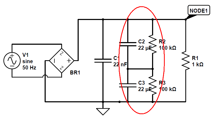
With capacitors in series they theoretically share half the supply voltage between node1 and ground. If that voltage is (say) 100V and you only have 63V rated caps, you can place them in series to get 50V across each cap and prevent each from damage. That's the theory.
In practice, it is advisable to bias the midpoint at half voltage with the two resistors to overcome differences in leakage currents on each cap offsetting the theoretical midpoint. The resistor values can be quite high but they do need to be significantly smaller in value than either of the equivalent worst-case equivalent leakage resistances of the caps.
-
\$\begingroup\$ even though we are using a 22nF as filter, why do we need an another capacitor ? \$\endgroup\$– noufalCommented Jun 21, 2013 at 9:02
-
\$\begingroup\$ @noufal for the power supply to provide smooth dc voltages to heavy loads 22nF is not enough and as 22uF/2 is 500 times more, it is a step in the right direction. On a lot of power supplies for (say) audio stuff a 1000uF or more will be used. \$\endgroup\$– Andy akaCommented Jun 21, 2013 at 10:51
-
\$\begingroup\$ I want to ask a similar but opposite question, why is the 22nF capacitor there in the first place? This is not the first time I'm seeing parallel capacitors with a few orders of magnitude difference. Mathematically, I think the difference is negligible: 11uF+22nF= 11.022uF. But obviously, there must be a reason for it being there. Why? \$\endgroup\$ Commented Feb 20, 2014 at 0:17
-
\$\begingroup\$ To give another example is a circuit I saw recently. A DC/DC converter MAX1674 chip. The output voltage line has 2 capacitors, one 47uF and one 0.1uF. I mean even the tolerance range of the 47uF capacitor is big enough to engulf the 0.1uF no? laserpointerforums.com/attachments/f42/… \$\endgroup\$ Commented Feb 20, 2014 at 0:22
-
1\$\begingroup\$ @midnightBlue a big electrolytic capacitor is probably very poor at attenuation frequencies above 10kHz whereas a 22nF will be good all the way to tens and possibly hundreds of MHz. \$\endgroup\$– Andy akaCommented Feb 20, 2014 at 0:27