8
\$\begingroup\$

At work, we are measuring various parameters to test out a newly designed oven prototype. To make things more efficient, I am trying to create an electronic setup to automate the measurement, in particular of the door's motion (from fully open to fully shut).

The goal is in measuring the instantaneous velocity of the door at the various points of its motion, which is a fixed radial path. Note the emphasis on instantaneous velocity logging, as opposed to an average velocity as determined by timing alone.

What is a way I can measure the ovendoor's velocity / track its motion with reasonable accuracy? (Reasonable implying error < 1-2 cm/s)

Since it is only fixed radial motion (and no component along any other axis), and since there is a moving component and a stationary component, I presume this should be an easier problem than, say, measuring the velocity of an independent body like a person or hand.

My first thought was an accelerometer-gyroscope-IMU-based method, i.e. integrating the acceleration over time to get the velocity, but reading up on this subject suggests that this will lead to sizeable errors.

\$\endgroup\$
4
  • \$\begingroup\$ Why don't you use ultrasonic devices? And measure time of reflection? Like in ultrasonic anemometers en.wikipedia.org/wiki/Anemometer#Sonic_anemometers , in you case wind will be door. \$\endgroup\$
    – sigrlami
    Commented Jun 22, 2013 at 19:06
  • \$\begingroup\$ Which part of the door are you wishing to measure the speed and what are your thoughts about getting different speed readings from different sections of the door (at different radii)? \$\endgroup\$
    – Andy aka
    Commented Jun 22, 2013 at 20:47
  • 1
    \$\begingroup\$ Perhaps the doppler effect could be used. Bounce a high frequency sound off the moving surface and monitor the echo returned for change in frequency compared to the original sound. You should be able to do this with a microcontroller. \$\endgroup\$ Commented Jun 22, 2013 at 21:31
  • \$\begingroup\$ @Andyaka: The speed of the door's center of mass. Although, since the door is a rigid body, a measurement of a point on the door edge should suffice just as well. \$\endgroup\$
    – boardbite
    Commented Jun 24, 2013 at 10:22

4 Answers 4

5
\$\begingroup\$

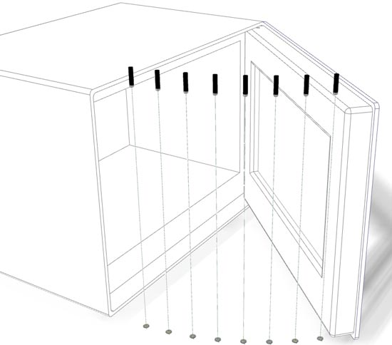
One suggestion is to have a set of inexpensive low power lasers arranged in an arc above the upper plane of the door's rotation, pointing directly downwards. A corresponding arc of PIN photodiodes or phototransistors just below the lower plane of the door's rotation can be hooked up to GPIO pins of a microcontroller, to detect the light interruption of each beam in sequence.

I've made a rough illustration of the arrangement, using 5 degree sensing angles. This precision could well be brought down to 1 degree per sensor, if needed.

Door Speed sensors

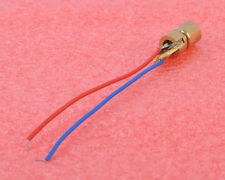
This 5 Volt 5 mW dot-type red laser would suffice (around $1 on eBay including international shipping):

Laser

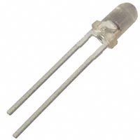
For the sensor, a PIN photodiode such as the OP906 ($0.59 in single units from Digikey) can be used:

PIN diode

In your microcontroller code, the timings for the successive laser beam interruptions will provide a precise instantaneous rotation speed between any two points separated by 5 degrees, as the door is opened or closed.

The ADC sample rate, timer precision and processing speed of the microcontroller will determine the data precision achievable.


One useful simplification of this design (thanks, @jippie, for getting me thinking in this direction), if precision is not super-critical, is to use a single narrow tube light, such as a 8 watt fluorescent or CFL tube, above the door, to replace the lasers. The light detectors would remain as they are, light to them would be interrupted in sequence as the door closes.

\$\endgroup\$
4
  • 1
    \$\begingroup\$ I've gone through a bunch of your answers, and they're always well-illustrated (in addition to being good answers!). What software do you use to create mockup graphics like the door illustration above? \$\endgroup\$
    – boardbite
    Commented Jun 23, 2013 at 9:54
  • 1
    \$\begingroup\$ @boardbite Depends on whichever software I would be currently using for my real-world work: Sometimes it is a manually drawn illustration in CorelDraw or PhotoShop, sometimes a CAD drawing in whichever CAD tool a given client has in their office, such as this one made in Inventor. \$\endgroup\$ Commented Jun 23, 2013 at 10:10
  • \$\begingroup\$ @Anindo: What a creative solution! Additionally, I could extend the LIGHT-DETECTED vs. LIGHT-INTERRUPTED discrete sensing further by taking an analog measurement of the light intensity. If my light source is the primary one in the setup environment, then based on the variation of the analog value of the light intensity, and some empirical data stored as a lookup table or as a fitting function, I could also infer the path of the door continuously, because I can estimate its position even when its center isn't exactly above one of the light-sensors/photodiodes. \$\endgroup\$
    – boardbite
    Commented Jun 24, 2013 at 10:31
  • 1
    \$\begingroup\$ @Inga Thank you. The narrow tube light option would lend itself to such analog position sensing, whereas for super-precise discrete sensing, the laser option would fit better. You could even do both at once, by positioning the tube just above the lasers. Good luck with the effort, and do share a photo of your implementation at some point, if you can. \$\endgroup\$ Commented Jun 24, 2013 at 11:01
5
\$\begingroup\$

I am not fully aware of the context of this oven door; but I would like to contribute a suggestion.

How about a quality potentiometer at the hinge of the door? Consider this, you get both the position and the velocity of the door this way; this method is simple and robust. Obtaining the position of the door is trivial, through some testing and measuring, you could find what values the pot outputs at given inputs, or door positions.

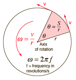
Also, if you differentiate the position with respect the time (in practice, you can simply divide the rate of change in position you obtain over the rate of change in time), you would get the angular velocity. Then from there you can calculate the velocity the door is traveling at.

enter image description here

From the picture above, the angular velocity would be little omega. V is the velocity the end of the door travels. V, obviously obtained with angular velocity multiplied by radius.

\$\endgroup\$
3
  • 1
    \$\begingroup\$ You differentiate once to get velocity, differentiate again to get acceleration, and differentiate a third time to get jerk. \$\endgroup\$ Commented Jun 23, 2013 at 4:26
  • \$\begingroup\$ @Nick: This sounds like a good, reliable (and quite computationally convenient) way to do it. The setup would eventually need to be easily transferable from one unit to another. Hence I am not sure how portable the above method is, given that an accurate measurement from a potentiometer/rotary-encoder would require a rigid connection with the hinge. Hmm, perhaps an easy fix for this could be achieved with some trial and error on the attachment style. \$\endgroup\$
    – boardbite
    Commented Jun 24, 2013 at 10:26
  • 1
    \$\begingroup\$ That does complicate things; the most pragmatic solution (at least that I can think of) if you wanted to go the potentiometer route would to build two small brackets, one to fit on the door and one to fit on the outside. These two brackets would link together via hinge. The pot would then measure this hinge's angular velocity. The practicality of this idea relies on whether or not you know someone who is good with metal work. Interesting project, best of luck! \$\endgroup\$ Commented Jun 24, 2013 at 13:06
3
\$\begingroup\$

I'm surprised that no one has mentioned using a string encoder or a string potentiometer It's a fairly simple and accurate solution. Basically a string is connected to a spring-loaded encoder and the encoder measures the string movement. There is very little moving mass and it doesn't require that the encoder shaft be colinear with the hinge or require any modification to the hinge such as gearing or belts.

\$\endgroup\$
2
\$\begingroup\$

If the primary movement is along a circular path, a single gyroscope should give sufficient accuracy. Would require some math to go from angular velocity to velocity of center of mass, but that's a one time calculation.

Basically, if the velocity is limited to angular velocity, a gyroscope+math can generally give you the instantaneous velocity.

The issue with IMU's and dead wreckoning type approaches is that over a long time you get compounding velocity error from integration of linear acceleration. This happens because there's generally no good way of generically determining linear velocity. This gets much worse when trying to determine position, accounting for rotational offsets of linear velocity, etc. etc.

Depending on the kind of testing you are doing, you can augment the IMU with a sensor for determining when the door is closed/at a stop position, then use that to re-zero the IMU. With that approach the IMU only needs to be reasonably accurate over the time it takes to open/close the door (presumably only a few seconds), which I believe is reasonable.

\$\endgroup\$

Your Answer

By clicking “Post Your Answer”, you agree to our terms of service and acknowledge you have read our privacy policy.

Not the answer you're looking for? Browse other questions tagged or ask your own question.