12
\$\begingroup\$

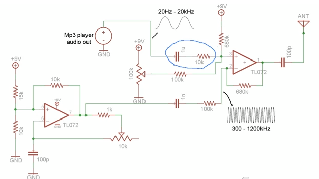
I found a very basic AM transmitter circuit on the youtube video here. The schematic is below:

schematic

I'm a bit confused on the op-amp circuit on the right. It seems that the op-amp is really only taking the difference between the message and carrier signals - not multiplying them together like it should be doing.

I'm not at all convinced that this part of the circuit is a frequency mixer. Am I just crazy?

\$\endgroup\$
1
  • \$\begingroup\$ I'm not convinced either. The second op amp is connected as a an inverting amp with a DC offset (100k variable etc.) The 'audio' signal is just moving this level up and down. \$\endgroup\$ Commented Jun 28, 2013 at 9:10

4 Answers 4

6
\$\begingroup\$

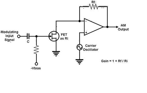
Further to my comment. You are quite correct about needing some form of multiplier. Perhaps the following addition could be made to improve the circuit. The FET acts as a voltage controlled resistor altering the gain of the op amp creating an AM signal.

enter image description here

\$\endgroup\$
6
  • \$\begingroup\$ JIm Derden always the analog guru ! \$\endgroup\$ Commented Jun 28, 2013 at 10:32
  • \$\begingroup\$ @sandundhammika Thanks. Andy makes a good point as well (so +1 from me) that by pushing the input of the op amp to its lower voltage limit it effectively sends the output to the rail. The audio signal lifts it out of this (non linear) region and will create some AM by accident rather than design. \$\endgroup\$ Commented Jun 28, 2013 at 10:45
  • \$\begingroup\$ Thanks for sharing the answer Jim. I was able to use a variation on this idea to get the circuit working reasonably well, although as I think you and Andy are indicating, this is only single-side band modulation(?) Details of the circuit & demo are available at github.com/tardate/LittleArduinoProjects/tree/master/… for any who care to crib. \$\endgroup\$
    – tardate
    Commented Sep 15, 2015 at 16:45
  • \$\begingroup\$ I think the am modulator designed using FET as posted by jim works. Here is more of it. appliedelectronicsengineering.blogspot.com/2015/10/… \$\endgroup\$
    – user88902
    Commented Oct 13, 2015 at 6:56
  • \$\begingroup\$ Apologies for bumping an old post. @JImDearden can't you just use a BJT transistor in place of the FET and OPAMP? \$\endgroup\$
    – Klik
    Commented Nov 26, 2015 at 0:20
2
\$\begingroup\$

Note the presence of the 100k pot - Why is it there? Does it perform some linear function in a summing amplifier? Not really - my guess is that it biases off the output against (say) the lower power supply rail (+1.5V for the TL072).

With no modulation signal, the carrier is not (or barely) present on the output of the final op-amp at all - the 100k pot ensures this. When a modulation signal is inputted the op-amp output is "lifted" out of output saturation thus allowing the "carrier" to break through and, it breaks through with an amplitude that is governed by the modulation.

Is it hi-fi? No - the output distortion on the radio is hard to tell (because it's a crappy little radio) but it will be something like AM.

Towards the end of the video it showed the waveform and that's exactly what is happening.

\$\endgroup\$
4
  • \$\begingroup\$ I agree I think the signal will suffer from a lot of distortion and will be hard to adjust the gains on that amplifier to get the receiver to pass the signal. \$\endgroup\$
    – user6972
    Commented Jun 28, 2013 at 18:12
  • \$\begingroup\$ @user6972 Absolutely but it is a great example of simple circuit non-linearites at work. It's also a pity that the youtube questions raised were not answered by the guy doing the voice-over in the video - folk are just not convinced by it because of the circuit "anomaly" \$\endgroup\$
    – Andy aka
    Commented Jun 28, 2013 at 18:40
  • \$\begingroup\$ Hmm...I'm having trouble understanding your answer. How does the 100k pot ensure that the carrier is not present on the output when there is no modulation signal? Also, I'm confused on what you mean by "output saturation" and the carrier "breaking through." Does that mean the the carrier has a voltage to swing from? Thanks for your help! I am pretty new to this if you haven't noticed :) \$\endgroup\$ Commented Jun 29, 2013 at 7:10
  • \$\begingroup\$ @superkittens The 100k pot can set the dc level on pin1 of the right-hand op-amp. If it were set in the middle of its range, the op-amp o/p on pin1 would be at 4.5V and you'd see the carrier waveform. Any modulating signal would just cause the carrier to ride along the slow moving (relative) modulating signal. This of course isn't AM, it's addition of signal A and signal B. However, the pot is setting pin1 to 1.5V (op-amp o/p is "pushed" against the lowest point it can go). The modulating signal drives the o/p away from 1.5V and the top of the carrier emerges "shaped" by the modulation. \$\endgroup\$
    – Andy aka
    Commented Jun 29, 2013 at 9:08
0
\$\begingroup\$

First, someone posting a youtube video or a web page is orthagonal to good design. In fact, if it's not a professional web page, it's more likely to be crap. Think about it. The guy that knows what he's doing and builds a quick and dirty AM modulator doesn't think anything special about it and probably won't post a web page. The guy that spent two weeks on random trial and error is much more likely to proudly post "Looky me world, I done made a modulator!!!".

Second, AM modulation isn't a pure multiply. That would be double side band. If you express AM as a multiply, you have to add a offset. It can also be thought of as adjusting the volume of a oscillator on the fly, which is not that hard to realize in analog electronics.

Now for the circuit. A TL072 is not a great choice for 1.2 MHz signals. This is most likely what this guy had in his junk box, which is more evidence this is less than a professional design. Lack of component designators is another strong clue.

However, this circuit could actually work well enough, within the limitation of the low gain of the opamp at the carrier frequency. Note that when the pot is at center, it biases the opamp at 1.6 V. Now look at the common mode range of the the TL072 and see the large headroom it needs on both ends. I think what is going on is that the modulation is performed by clipping the carrier at a different level depending on the modulation signal. The pot is adjusted so that the carrier is just about half clipped off with no input signal. That allows the input signal to cause the carrier to go all the way from 0 to full while idling at 50%.

You're probably thinking that would introduce horrible distortion. Yes it would, but note that this distortion is in the carrier, which is a fixed frequency. When looking at the frequency spectrum, distortion shows up as harmonics, which will occur at all integer multiples of the carrier frequency. So this modulation scheme introduces a lot of distortion components with the lowest being twice the carrier frequency. However, the radio that receives this will simply reject those components because they are way out of band. This modulator makes a mess at other frequencies, but at the frequency of interest it looks like it can work well enough.

Something like this would never pass FCC tests due to the large amount of out of band crap it radiates. But if you're just doing this accross a room with a small antenna, then the crap won't go very far and probably won't cause enough trouble so that someone complains.
\$\endgroup\$
-2
\$\begingroup\$

I haven't watched the video, but this might actually work. I haven't seen this technique before, but it is a sort of pseudo-am. They are using a difference amplifier with equal gain to both signals. The two pots are used to make minor adjustments to either the audio or the carrier gain. I have to assume this is a bit touchy to get right.

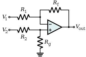
The difference amplifier topology is basically:

difference amplifer

If you set \$\frac{R_f}{R_1}=\frac{R_g}{R_2}\$ then the output is

\$V_o=\frac{R_f}{R_1}*(V_2 - V_1)\$

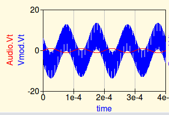
You're right that this isn't multiplying, but you do end up with an AC riding on the carrier that looks like this (blue is the pseudo-am output and the red is the audio input):

am mod?

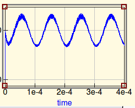
If you run that through a diode detector it will pass the AC portion into your low-pass filter with a variety of distortion depending on the balance of the transmitted signal and how hard the diode turns on.

enter image description here

I haven't spent the proper time to really look at this. However my quick analysis suggests that it might work. But it isn't AM modulation and there might be a lot of distortion as Andy Aka mentions due to non ideal conditions (which might even help introduce AM at the audio rate).


EDIT: It may not be obvious how this could work on an AM radio. The carrier biases on the receiver and the diode. No envelope is found so a typical receiver will adjust the agc gain up. This little transmitter is putting out a very strong amplified audio signal directly into the open wire (the 100pF couping cap is meaningless to this signal because the wire is open). There will definitely be some leakage directly to the AM receiver if is it close by. Most AM receivers don't have much filtration below 500Khz on the input and the audio section which is on and running hard just has to pickup some of the coupled signal. Filtration will be strongest in the IF, however depending on the architecture you could even pick a RX frequency where the image lies in 1Khz to 15Khz (or in the 2nd or 3rd filter harmonic) and get some help from the IF amps. While no one would do this on purpose, I can see how this could be made to work in the demo without actually having a normal AM input.


Edit2: Look, if this works, it's only because AM receivers are highly susceptible to noise from a variety of sources including direct feed through, which is what I'm suggesting. The carrier is biasing on the AM receiver but there is no modulation on the carrier itself so the only thing the backend picks up is noise and it's going to crank up its gain. This allows the amplified audio to feed through (I suggested a few probably paths) which won't work reliably and probably only works for this guy's setup because they are in very close proximity. If you've ever heard 60hz hum on your experimental AM radio in the lab or perhaps your car's alternator buzzing on the AM radio, it's a similar effect.

\$\endgroup\$
9
  • \$\begingroup\$ It would be interesting to see what the pseudo-am signal looks like in the real circuit. Is the audio really shutting off the carrier due to the bias conditions as Andy suggests? \$\endgroup\$
    – user6972
    Commented Jun 28, 2013 at 18:31
  • 1
    \$\begingroup\$ No, that's not how AM demodulation works. Remember that a AM receiver starts with a very narrow band filter. The modulation signal in your first plot is just added to the carrier and will be rejected by this filter. Think of it in frequency space. Your whole premise is just plain wrong. Another way to think of this is that the "diode detector" you mention won't ever see the signal in the first plot. \$\endgroup\$ Commented Jun 28, 2013 at 19:32
  • \$\begingroup\$ @OlinLathrop I agree with you, however it depends on how the TX/RX system is setup in the demonstration because with just a weak bandpass (used in the graph I made above) the AC signal comes through enough to be detected. I understand it goes against the grain, but I'm just looking at how it might be made to work. It's outside the box. \$\endgroup\$
    – user6972
    Commented Jun 28, 2013 at 23:39
  • \$\begingroup\$ I just went to the link to see what was there but my cell data connection is too poor to even begin viewing it. If he's using a similar crappy homemade detector then he's probably not getting much filtering across the whole band. Thanks for the down vote anyway. \$\endgroup\$
    – user6972
    Commented Jun 28, 2013 at 23:54
  • 1
    \$\begingroup\$ You are missing the point that the 10 kHz audio signal won't propagate off the antenna. From the point of view of RF that is basically DC, and DC is lost in radio transmissions. The only way your scheme could work is with a direct wire connection that can carry the low frequencies, but that's not what is being talked about here. Note the output of the second opamp clearly going into a 100 pF cap and antenna. 10 kHz simply isn't going to make it to any receiving antenna, even if the receiving tuner doesn't filter it out somehow. Think about your waveform in frequency space. \$\endgroup\$ Commented Jun 29, 2013 at 13:59

Not the answer you're looking for? Browse other questions tagged or ask your own question.