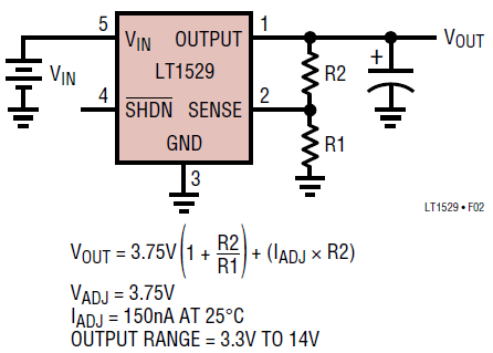
I'm using a LT1529 voltage regulator and I'm having a hard time understanding the process for determining the resistors to use in the voltage divider. The datasheet provides the following schematic and calculation:

ADJ (Pin 2): Adjust Pin. For the LT1529 (adjustable version) the ADJ pin is the input to the error amplifier. This pin is internally clamped to 6V and – 0.6V (one VBE). This pin has a bias current of 150nA which flows into the pin. See Bias Current curve in the Typical Performance Characteristics. The ADJ pin reference voltage is equal to 3.75V referenced to ground.
I want an output voltage of 4.0V. The typical ADJ pin bias current (which I think is the desired current for the adj pin) is 150nA. I'm not sure if I should use these values to determine the R2 resistor. It gives a rather large resistance value (like 26.6M). Once I know R2, R1 should be easy to solve for but I would appreciate confirmation on that value too.
