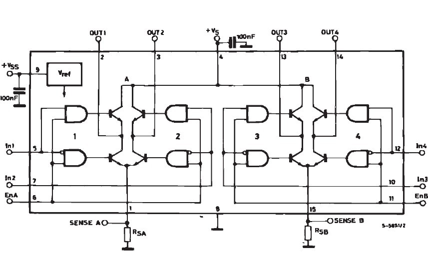
Given the below H-Bridge, how do you calculate the current through the conduction paths? This particular IC, the L298, has a per-bridge limit of 2A - so I know the upper limit.
If I were to place a motor across the leads then, based on the motor's load, I would have a rough idea via the datasheet of that motor.
But what if I were to place a resistor across OUT1 and OUT2, or short them?
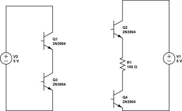
If shorted:
The entire supply Vs would appear across two transistors. Would it simply be distributed as Vs/2 per transistor? How would you calculate the associated current?
Does the answer lie withing this characteristic?:

So, does this mean that if the transistor has 400mV across the collector-emitter junction thn the current will be saturated at 150mA? So that is, with two of these transistors and OUT1 and OUT2 shorted together, terminals in the below bridge would have 150mA through them since the supply (if the supply Vs is greater than 800mV) would be across their junctions?
How would you calculate the current if the terminals were not saturated - or do transistors in this application always operate in saturation mode?
If OUT1 and OUT2 are tied together with a resistor:
If the supply is greater than 800mV, will the transistors automatically be in saturation mode with 150mA of current draw (for the 2n2222)? If so, the voltage across some resistance R connected across the terminals of OUT1 and OUT2 would then be 150mA*R.
And consequentially, would the voltage across the transistors would be Vt = (Vs-150mA*R)/2?

Basically, what I am asking is how to calculate the current in the following two configurations:

simulate this circuit – Schematic created using CircuitLab
Assuming that transistors are biased with base current as shown in the above IC schematic. How would you calculate the voltage across the resistor and the current in either case?

