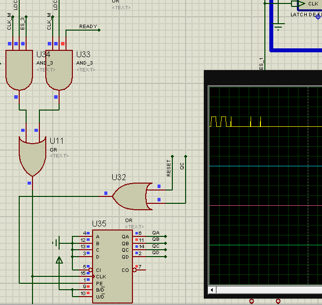
I have a circuit in Proteus with a few logic components (logic gates, counters, comparators, adders, etc).
I have a 3 input AND gate which two of the inputs are '0' and the other one is a Clock signal, even when 2 of the inputs are '0' I have some transients in the output signal of my and gate as you can see in this picture, I don't know if it is intended or a Proteus bug:

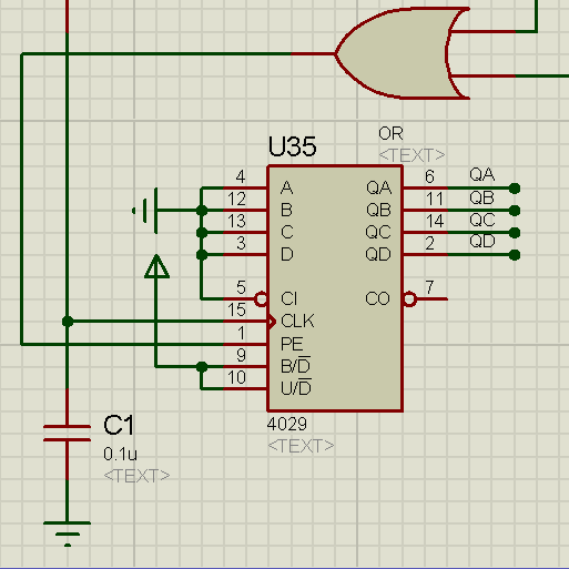
So I solved this putting a .1 uF capacitor to ground in my 4-bit counter clock input and everything is working perfectly.
Now I want to package this circuit in a component to use it in another schematic as I always do, I create my component and attach to it a hierarchy module which is the circuit I created. The problem is that when I add the capacitor on this way:

When I execute the simulation I get this errors:
SPICE failed to connect pin V+! U45_U2_#P
Node U45_VDD not found whilst binding pin V+ of U45_U8_ADC#0001!
If I disconnect the capacitor only to from the IC simulation works but I got the problem with the clock, no matter where I connect the capacitor, If I connect it to any IC I get this error. Why? How can I get it working?
The circuit is working perfectly but when I put it inside the component I get this error. I am using Proteus 7.7 SP2.
