15
\$\begingroup\$

In a (tentative) new design I want to connect two 100 Mbit/s Ethernet PHY similar to LAN8270a, separated by few inches on the same PCB, with same ground plane (but different power supplies). I have the choice of one of my PHY, but the other is embedded in an as-yet-unspecified PCIe to Ethernet IC (perhaps Gigabit but used in 100 Mbit/s mode), and it is critical that this PHY thinks there is a bona fide 100 Mbit/s Ethernet connection.

I could use the following
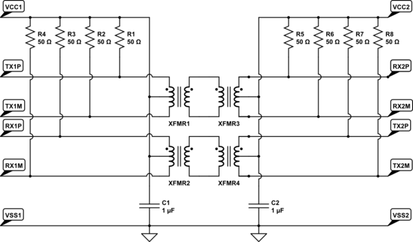
schematic

simulate this circuit – Schematic created using CircuitLab

but I would like to achieve the same without the magnetics, in order to save on cost, purchasing headaches, and if at all possible power consumption.

I can imagine an RC network, perhaps as simple as in this appnote, found thanks to a similar question; or maybe engineered with attenuation and lowpass, but that will not emulate the fact that with real magnetics, when there is a negative pulse on TX1P, there is a positive pulse on TX1M and RX2M. I am uncertain about if that would prevent some PHYs from working normally.

Anything to suggest that one is confident will work for practically any PHY around?

\$\endgroup\$
3
  • 1
    \$\begingroup\$ At the very least, you can eliminate one transformer in each path from the circuit you show. There are 1:1 ethernet transformers that have center taps on both sides. \$\endgroup\$ Commented Nov 12, 2013 at 16:35
  • 1
    \$\begingroup\$ @Olin Lathrop: Right. I wish I had found such transformer in CircuitLab too! \$\endgroup\$
    – fgrieu
    Commented Nov 13, 2013 at 7:13
  • 5
    \$\begingroup\$ Note that ethernet has a 1 metre distance expected as a minimum distance between ports (for standard PHYs) and you may need to capacitively load the interconnect to achieve an equivalent distance electrically. This bit me on a project a few years ago. \$\endgroup\$ Commented Oct 22, 2015 at 17:49

4 Answers 4

10
\$\begingroup\$

You might be interested by these Application Notes about transformerless/magnetic-less ethernet application

They both have an example of transformerless operation on a PCB, with a capacitor in place of a transformer. In a case where you control both side of the connector, only one capacitor on the line can be mounted. But if you control only one side you have to put a capacitor two, in case the other side has nothing or has a transformer.

I had to work on a 1000Base-KX backplane connection, and its problem is this standard is not very well known and you can have difficulties to implement it, have information about it, etc.

In my case I needed to have an oscilloscope pattern to observe the signal. After few email to the oscilloscope company and few phone calls I had them understood that I was talking about 1000Base-KX and not 1000Base-CX (Ethernet over Coax).

The 1000Base-KX was "retro-implemented" in the IEEE802.3 when the 10GBase-KX was created. So the 1000Base-KX is a standard derived from 10G and officially become a IEEE standard years after the adoption of the Gigabit standards.

Also 1000Base-KX only need 2 pairs (Full-Duplex) but the operating frequency is around 1Ghz which involves signal integrity issues where 1000Base-T and 100Base-T(X) stays at 125MHz.

\$\endgroup\$
3
  • 1
    \$\begingroup\$ The fact is transformerless application is quite rare and not very well documented. Each vendor has its own implementation, as these AN show it. You should find a PHY which is closely related to its PHY and find an AN about transformerless application from the IC vendor. But without information, the best thing will be practical implementation and tests with different capacitor values and resistors. \$\endgroup\$
    – zeqL
    Commented Nov 12, 2013 at 16:11
  • 1
    \$\begingroup\$ Spot-on references! Note: I fear the Intel AP-438 Figure 1 might not work with quite all PHY, for there is no pull-up of TX lines to Vcc, radically modifying the DC biasing. TI AN-1519 Figure 5 has DC bias (on both Tx and Rx), and (combined with Figure 10 C) seems likely to fit my needs; basically the transmormer(s) are replaced with 4 caps. [repost with correction] \$\endgroup\$
    – fgrieu
    Commented Nov 12, 2013 at 17:31
  • 1
    \$\begingroup\$ While I agree that "transformerless" operation is less standardized/documented than it should be, it's hardly a rarity these days (with all the blade systems around, be it ATCA/uTCA based industrial gear or a random Dell/HP/whomever blade server rack). \$\endgroup\$
    – oakad
    Commented Nov 13, 2013 at 3:28
6
\$\begingroup\$

What you really need is a different variety of PHY, so called "backplane phy". Those are specifically designed to work with capacitive coupling over PCB traces.

The relevant standard is called 802.3ap. Here's a nice overview: ftp://ftp.t10.org/t10/document.05/05-214r1.pdf

Many modern PHYs can be put into a 1000Base-KX mode through a bit of configuration tweaking.

One long running and popular PHY of the above variety, which can be frequently found on all kinds of expansion boards is Marvel 88E1145: http://www.marvell.com/transceivers/assets/Marvell-Alaska-Quad-88E1141-45-GbE.pdf

Many integrated Ethernet controllers also support this mode of operation (Intel as an example): http://www.intel.com/content/dam/doc/application-note/82545-82546-82571-82572-631xesb-632xesb-gbe-controllers-serdes-design-appl-note.pdf

\$\endgroup\$
2
  • 1
    \$\begingroup\$ Thanks for the pointers. My use case is a PCIe board that appears as a 100% vanilla Ethernet board, with the key objective that bundled drivers in most OSes will recognize it without change; thus I have to use regular 100BASE-TX, no way to teak registers in that PHY. \$\endgroup\$
    – fgrieu
    Commented Nov 12, 2013 at 8:29
  • \$\begingroup\$ I could be mistaken but I think many common ethernet controllers can load their configuration from an attatched EEPROM rather than relying on the host to set it. \$\endgroup\$ Commented Oct 22, 2015 at 15:57
2
\$\begingroup\$

The transformers are there to help impedance match to an RJ45 Ethernet line so if you're confident that the impedance match you will be fine even for tens of feet.

Small print

Transformers also protect silicon from line disturbances that might otherwise kill silicon so be aware of this. They also isolate galvanically the two systems and stop earth loops passing currents that can cause poor data quality. Providing you don't need to have a dc level on the connection (that is usually harnessed via a transformer centre-tap) and you have both systems connected thru capacitors it should work. Read the datasheet.

\$\endgroup\$
4
  • 1
    \$\begingroup\$ I can't read past the unbalanced parenthesis... \$\endgroup\$
    – Samuel
    Commented Nov 11, 2013 at 21:22
  • \$\begingroup\$ @Samuel - is that OK dude - I had an extra bracket!! \$\endgroup\$
    – Andy aka
    Commented Nov 11, 2013 at 21:36
  • \$\begingroup\$ That sentence wasn't compiling. \$\endgroup\$
    – Samuel
    Commented Nov 11, 2013 at 21:56
  • \$\begingroup\$ @Samuel LOL - it showed up ok on IE \$\endgroup\$
    – Andy aka
    Commented Nov 11, 2013 at 22:04
1
\$\begingroup\$

Etherent uses various types of line codes to ensure that the transmitted data is DC balanced. 4b/5b is the line code used in 100 Mbit ethernet, and then it is transmitted with MLT-3 encoding. The 4b/5b code caps the number of ones and zeros you can get in a row. Then MLT-3 transmits three different voltage levels, -1, 0, and +1. A transition represents a 1 and no transition represents a zero. So it doesn't matter if the line is inverted or not as the transitions carry the information, not the levels. Now, it's possible that some PHY chips will not be able to drive something that's not a transformer, so you may have a problem there depending on how it's connected. I think that would only be a problem if the ouputs are open collector instead of push-pull. You should be able to get away with one transformer, though.

\$\endgroup\$

Your Answer

By clicking “Post Your Answer”, you agree to our terms of service and acknowledge you have read our privacy policy.

Not the answer you're looking for? Browse other questions tagged or ask your own question.