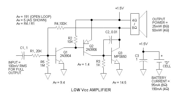
I have to analyze an amplifier circuit for 8 ohms, 0.025 watts speaker and don't understand how it works. What is the working principle of the components? What configurations are used? In which stage does the amplification take place? What biasing are used and why?
-
\$\begingroup\$ The configurations are all common emitter. In the last one, the speaker serves as the load, so the stage basically drives current through it. Amplification takes place in all the stages. Resistors R5 and R3 are quite pointless without emitter resistors on Q1 and Q3. R4 provides global negative feedback, C2 is "dominant pole compensation". \$\endgroup\$– KazCommented Dec 6, 2013 at 3:47
-
\$\begingroup\$ Did you mean to say 25 watts in the title or just 0.25 watts? \$\endgroup\$– Andy akaCommented Dec 6, 2013 at 11:56
-
\$\begingroup\$ or 0.025W @Andyaka ;o) \$\endgroup\$– jippieCommented Dec 6, 2013 at 13:23
-
\$\begingroup\$ just 0.025 watts. \$\endgroup\$– Kaiju19Commented Dec 6, 2013 at 13:37
-
\$\begingroup\$ Can someone please explain to me, why is that there is a resistor after c1? \$\endgroup\$– Kaiju19Commented Dec 6, 2013 at 13:40
1 Answer
Can someone please explain to me, why is that there is a resistor after c1?
With this amplifier topology the global gain is defined by \$A=\dfrac{R4}{R1}\$, provided that the open loop gain from the transistors is much higher than that.
In that the base of Q1 will act as virtual ground for the AC signal. Notice that for DC the base is biased to approximately 0.6V. With R1 at (virtual AC) ground, your input impedance equals R1.
A simplified opamp circuit would look like this (notice that it will not work in practice due to low voltage).
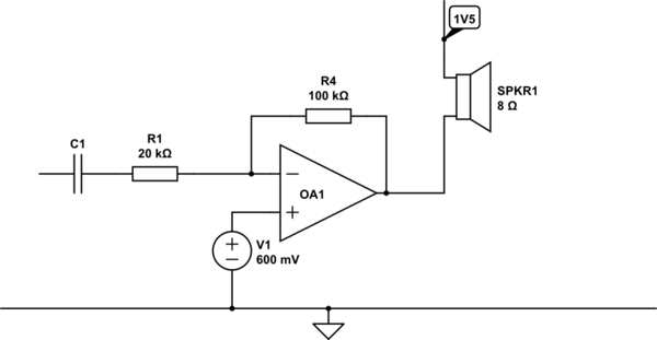
simulate this circuit – Schematic created using CircuitLab