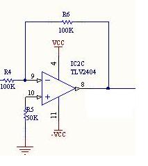
Here in the Figure R5=50K. This resistor value is not in the equations to obtain output voltage, and in many tutorials non-inverting input is directly grounded without a resistor. What might be the reason to use it here?

Here in the Figure R5=50K. This resistor value is not in the equations to obtain output voltage, and in many tutorials non-inverting input is directly grounded without a resistor. What might be the reason to use it here?
R5 equals R4 || R6 (resistors in parallel) calculated as $$R_5 = \frac{R_4 \cdot R_6}{R_4 + R_6}$$ and its purpose is to balance the two inputs of the opamp, it cancels the differences caused by the opamp input bias current
http://www.ecircuitcenter.com/Circuits/op_ibias/op_ibias.htm
DC balance, aka input offset compensation.
Some opamps take a significant input current on each input pin - let's say 1 microamp. Work out the input impedance on the -ve input : 2 * 100k in parallel, giving 50K input impedance. Now that microamp input drops 50mv across that resistor, giving an output voltage of 50mv * the gain.
R5 compensates for this by dropping a matching 50mv on the other input, restoring the DC output to its correct value.
In practice there is also a voltage difference and a slight current imbalance between the inputs; called "input offset voltage" and "input offset current" which vary between amplifiers. This leaves an imbalance of (50k * offset current) + offset voltage at the input.
Some opamps draw tiny input currents; using these you can omit R5.