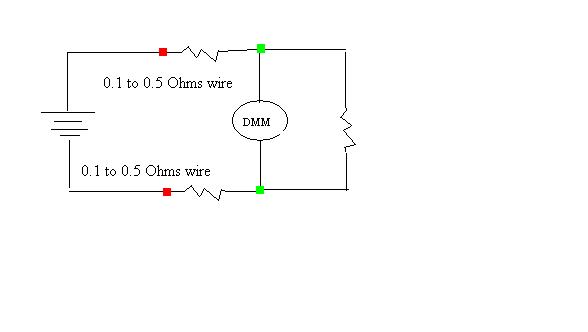
I have a DC/DC converter outputting 5.18 VDC @ 25% load (1 Ohm resistor). If I measure the voltage at the green nodes it fails out of tolerance, if I measure the voltage at the red nodes (before the line resistance) it passes tolerance. (See Figure 1)

The tolerance is 5.18 VDC +/- 0.155 VDC.
There is a line resistance of 0.1 to 0.5 ohms on each output, the wiring is pretty long in this case. I understand there is a voltage drop proportional to current flowing, at this case there is about 1.75 A flowing at 25% load.
1.75A * 0.5 Ohms = 0.875 VDC Voltage drop for each output wire. I get why that is failing.
However when I am measuring the voltage output at the red nodes, it is in tolerance, but the same line resistance 0.875 VDC voltage drops are still connected to the load resistor because the current is still flowing through them to get to the load (in parallel with the DMM). So why does this pass? Wouldn't the line resistance add to the load resistance in either case?
