9
\$\begingroup\$

Before I ask my question, I should say that I am very new to working with electronics and I may not quite know how to describe my problem.

I am trying to use a pin on my msp430 microcontroller I have as a replacement for a pushbutton on a device. The msp430 is 3.3v and the device I am switching is 5 volts. I was under the impression I could use a 2n3904 transistor in place of the button by applying current by turning on the pin on the msp430 which would let current go from the collector to the emmiter, and hopefully "push" the button.

This is my current setup
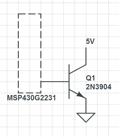
However, turning the pin on does not activate the circuit. When I connect the jumper for the onboard LED, I can verify the pin is working. also, when I connect the 5v from the collector to the base using a wire, I can activate the transistor.

What other information am I missing to solve this? Thanks in advance

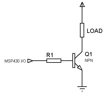
EDIT: After reading the comments, adding a 4.6k resistor between the base and IO pin and connecting my 3v ground and 5v ground allowed me to control the transistor without any noticeable problems. Thank you!

\$\endgroup\$
6
  • \$\begingroup\$ See electronics.stackexchange.com/a/91899/2191 \$\endgroup\$ Commented Jan 6, 2014 at 18:43
  • \$\begingroup\$ IF you connected the 5V to the base WHILE it was connected to the MSP430... uC pin then you may have damaged the uC. Also, connecting 5V to the transistor base correctly is likely to damage or destroy the transistor. The Vbe junction usually operates at about 0.6 to 0.8V. Actual voltage is "set" by the transistor and is based on the current supplied via (usually) a resistor. As Ricardo says, 10k resistor should be about right. If that does not work then uC pin (or more) may be damaged. \$\endgroup\$
    – Russell McMahon
    Commented Jan 6, 2014 at 18:58
  • \$\begingroup\$ I doubt if the microcontroller pin is damaged. The short circuit current for a single MSP430 output pin looks like about 45mA and I don't think that would hurt the microcontroller or the transistor. Since the controller is a 3.3V part the power dissipation will be around 100mW, the base-emitter power dissipation is about 40mW. \$\endgroup\$
    – Joe Hass
    Commented Jan 6, 2014 at 19:17
  • \$\begingroup\$ The replies given below seem to assume that what you want to do is a low side switch, is this the case? How is the button that you want to replace wired? Does it connect Vcc (5v) to the circuit it drives or ground? \$\endgroup\$
    – alexan_e
    Commented Jan 6, 2014 at 19:42
  • 1
    \$\begingroup\$ I hope you can understand how confusing you schematic is. Having 5v connected to the collector without showing that it comes from a pullup resistor or the pull down button that your tryng to override doesn't help us understand the problem in order to help. Please next time include all relevant components in the schematic. \$\endgroup\$
    – alexan_e
    Commented Jan 6, 2014 at 20:21

3 Answers 3

8
\$\begingroup\$

It looks like you need a current limiting resistor between your output pin and the transistor base (assuming you didn't omit it on purpose, for brevity). Without the resistor, when you set the output pin to HIGH, you are causing a short-circuit to ground. That may damage the pin, if it hasn't done so already.

I would guess that a 10K resistor would do it. That's what I use with my ATmegas and ATminis. But check your MCU datasheet for appropriate values.

It's quite a common mistake to think that the base-emitter junction already has some sort of current limiting property, but it doesn't. It has very low impedance. I usually think of it as a plain wire. That helps me avoid these kinds of mistakes. Same applies to collector-emitter junction.

By the way, your collector-emitter path has no current limiting resistor or load. Watch out! 

\$\endgroup\$
6
  • \$\begingroup\$ Thanks for the answer. I should add that before the button i am trying to interface with there is a 4.6k resistor on the collector side. also as i dont have a lot of resistor choices available, is there a range of resistors i can use, I am currently just salvaging parts from a few pcbs i have laying around. thanks! \$\endgroup\$
    – Strayermm
    Commented Jan 6, 2014 at 19:09
  • 1
    \$\begingroup\$ I guess you could use any resistors from 1K to 10K, but you should read the datasheet to be sure. Look for the maximum current that an output pin can source and then calculate the resistor using V=R.i so that the current is no more than half that value. That's because maximum values are usually TOO MUCH. \$\endgroup\$
    – Ricardo
    Commented Jan 6, 2014 at 19:16
  • \$\begingroup\$ Here's a link to a datasheet, but I'm not sure it applies to your MCU. \$\endgroup\$
    – Ricardo
    Commented Jan 6, 2014 at 19:19
  • \$\begingroup\$ Well, your MCU is WAY over my head. I'm more familiar with AVR's ATmega328 and ATtiny85 which usually can source up to 20mA per output, 100mA total per MCU. Yours seem to source less than that, so I would use resistors from 5K and up. But better wait for guidance from more experienced users. \$\endgroup\$
    – Ricardo
    Commented Jan 6, 2014 at 19:22
  • \$\begingroup\$ With MSP430, I had success with a 10K ohm resistor. Anything in that ballpark should probably work. \$\endgroup\$
    – Marsh
    Commented Jan 6, 2014 at 19:26
6
\$\begingroup\$

Your circuit will only work as a low side switch, meaning that it should be connected to the ground side of the load like

Low side NPN switch

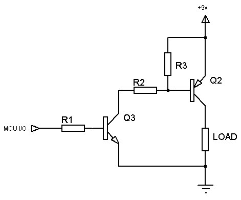
If I understand correct you want to make a high side switch (connected to the Vcc side of the load). In that case you'll need a PNP used as

High side PNP using NPN translator

(I made the schematic for a similar question so don't mind the 9V supply, it's the same for 5V)

Please read my reply to Arduino, NPN and common cathode RGBs.

\$\endgroup\$
2
  • 1
    \$\begingroup\$ Can I know what is the point of R3 ? \$\endgroup\$
    – xmen
    Commented Feb 22, 2015 at 9:50
  • 4
    \$\begingroup\$ @xmenW.K. The collector-base capacitance of Q2 can slow switching when Q3 turns off, so R3 can speed up turn off by pulling the base high. The other reason is to bleed off leakage currents of Q2 that may turn the transistor on. It also shunts noise signals that may also turn the transistor on. \$\endgroup\$
    – alexan_e
    Commented Feb 22, 2015 at 11:37
4
\$\begingroup\$

In addition to a current limiting resistor mentioned by Ricardo, you'll also want to make sure that both the 3.3v MSP430 and the 5V device have their grounds connected. This will make 0V for the MSP430 be the same potential as 0V for the 5V device.

I just finished a project this weekend where I used an MSP430 G2553 to control the power and function buttons of a cheap camera with transistors, and had this exact same problem. I had to add current-limiting resistors, and I have to make sure the emitters and collectors of the transistors were wired up to the buttons correctly. Before I added the resistors, it seemed like my power button/transistor was working, but really I had been shorting through the transistor and the camera was reading the high on the MSP430's pin directly.

For reference, my question from a few days ago.

\$\endgroup\$

Your Answer

By clicking “Post Your Answer”, you agree to our terms of service and acknowledge you have read our privacy policy.

Not the answer you're looking for? Browse other questions tagged or ask your own question.