1
\$\begingroup\$

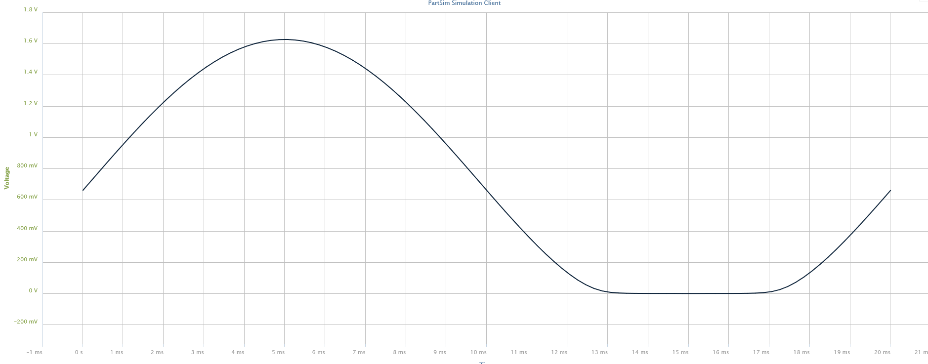
After tweaking the domains, the run-time duration of the simulation and the location of the probe I discovered that there was no mistake. Below I've attached a picture of the graph blown-up.


Recently I've become interested in self-studying electrical circuits and upon my scholastic quest I've stumbled upon a problem.

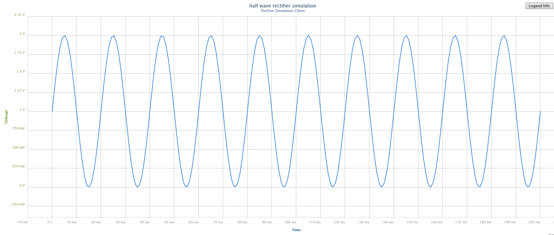
To my understanding, a half-wave rectifier is meant to eliminate the "negative portion" when graphed using a sine representation when tested on a simulator, but I don't seem to be getting the same result.

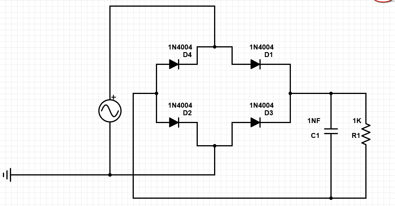
The other problem that I'm facing is trying to run a simulation of a full-wave rectifier.

I'm using PartSim, which is a completely free simulator (Not an expert with it... yet).

I'll attach some pictures of the circuits that I made and also the apparent simulation results.

Thanks in advance!

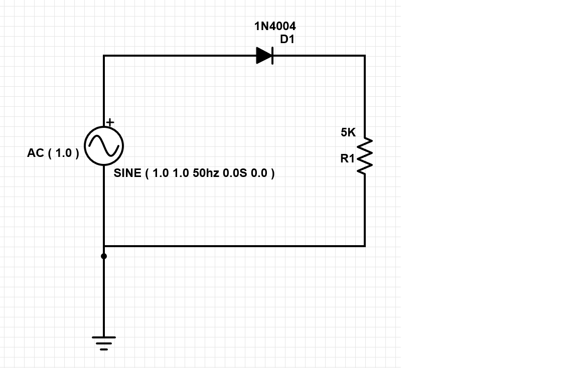
My Diagram of Half Wave Rect: Half Wave Rectifier
Graph of Simulation of Half Wave Rectifier: Simulation of Half Wave Rectifier
Zoomed in Depiction of Graph: Correct Graph

My Diagram of Full Wave Rect: Full Wave Rectifier

\$\endgroup\$
5
  • \$\begingroup\$ Are you sure you place the probe at the correct location? That is to say the net between the diode and the resistor? \$\endgroup\$
    – AndrejaKo
    Commented Feb 7, 2014 at 13:39
  • \$\begingroup\$ Electrical and electronics it is not a "push button" matter or the "like" button on f/b. It is a science that includes personal skills, deep knowleges about the subject, many years spends on schools and involves, physics, mathematics, chemistry, philosophy, humor, sharp mind, friends.... just to count what is not on my side. I will watch here to learn together \$\endgroup\$
    – GR Tech
    Commented Feb 7, 2014 at 13:43
  • \$\begingroup\$ @AndrejaKo, yes I believe so. \$\endgroup\$
    – JCC
    Commented Feb 7, 2014 at 14:42
  • \$\begingroup\$ The "zoomed in depiction of graph" is not what you say it is. Have you read the very valid answer given by CAGT - your own answer explains nothing. What are you trying to do? \$\endgroup\$
    – Andy aka
    Commented Feb 11, 2014 at 12:25
  • \$\begingroup\$ Why do you have a 1v offset \$\endgroup\$
    – user16222
    Commented Feb 12, 2015 at 19:00

1 Answer 1

1
\$\begingroup\$

The problem I see with your schematic is that you have two ground references. Your AC power supply is grounded, as well as D2 cathode. And the bridge rectifier DC output rail's ground is in fact the anode of D2 (even though not shown), the cathode of D3 being the positive (Vcc). Also note that your load R1 is connected between these two points. Now, am I missing a point or are both the anode and cathode of D2 grounded (D2 shorted)?

\$\endgroup\$

Your Answer

By clicking “Post Your Answer”, you agree to our terms of service and acknowledge you have read our privacy policy.

Not the answer you're looking for? Browse other questions tagged or ask your own question.