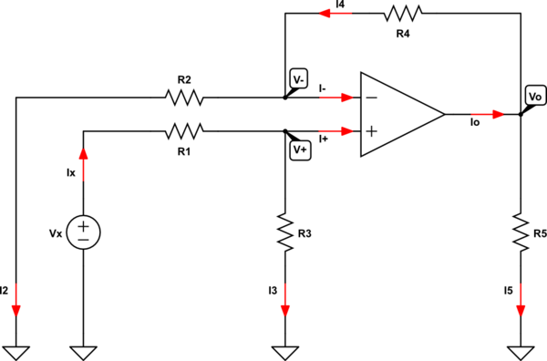
Well, we have the following circuit (and we assume an ideal model of an OPAMP):
<!-- Begin schematic: In order to preserve an editable schematic, please
don't edit this section directly.
Click the "edit" link below the image in the preview instead. -->

<!-- End schematic -->
Using KCL, we can write:
$$
\begin{cases}
\text{I}_4=\text{I}_-+\text{I}_2\\
\\
\text{I}_x=\text{I}_++\text{I}_3\\
\\
\text{I}_\text{o}=\text{I}_4+\text{I}_5
\end{cases}\tag1
$$
Using KVL, we can write:
$$
\begin{cases}
\text{I}_x=\frac{\text{V}_x-\text{V}_+}{\text{R}_1}\\
\\
\text{I}_2=\frac{\text{V}_--0}{\text{R}_2}\\
\\
\text{I}_3=\frac{\text{V}_+-0}{\text{R}_3}\\
\\
\text{I}_4=\frac{\text{V}_\text{o}-\text{V}_-}{\text{R}_4}\\
\\
\text{I}_5=\frac{\text{V}_\text{o}-0}{\text{R}_5}\\
\\
\end{cases}\tag2
$$
***Notice***: in the ideal OPAMP circuit we assume that \$\text{I}_+=\text{I}_-=0\$ and \$\text{V}_+=\text{V}_-\$.
Now, the gain is defined by:
$$\text{G}:=\frac{\text{V}_\text{o}}{\text{V}_x}\tag3$$
We can find an expression for the output voltage \$\text{V}_\text{o}\$, by solving the systems of equations:
$$\text{V}_\text{o}=\frac{\text{V}_x\text{R}_3\left(\text{R}_2+\text{R}_4\right)}{\text{R}_2\left(\text{R}_1+\text{R}_3\right)}\tag4$$
So, we get:
$$\text{G}=\frac{1}{\text{V}_x}\cdot\frac{\text{V}_x\text{R}_3\left(\text{R}_2+\text{R}_4\right)}{\text{R}_2\left(\text{R}_1+\text{R}_3\right)}=\frac{\text{R}_3\left(\text{R}_2+\text{R}_4\right)}{\text{R}_2\left(\text{R}_1+\text{R}_3\right)}\tag5$$
>In your case we get:
>
>$$\text{G}=\frac{68000\cdot\left(30000+63000\right)}{30000\cdot\left(12000+68000\right)}=\frac{527}{200}=2.635\tag6$$
____
Solving it, in general, gives (notice that \$\text{V}_+=\text{V}_-=\text{V}_\text{p}\$:
[![enter image description here][1]][1]
In your case (using your values):
[![enter image description here][2]][2]
>I checked my solution using LTspice and I got it right.
[1]: https://i.sstatic.net/5bHt7.png
[2]: https://i.sstatic.net/3KdmJ.png