<!-- Begin schematic: In order to preserve an editable schematic, please
don't edit this section directly.
Click the "edit" link below the image in the preview instead. -->

<!-- End schematic -->
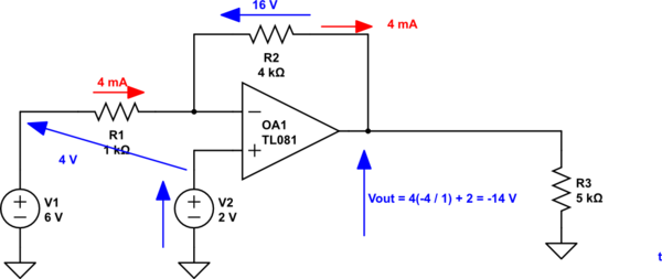
_Figure 1. Inverting op-amp with offset on non-inverting input._
- The trick here is to remember that the op-amp doesn't know where your GROUND or 0 V is. This should be obvious from the schematic as there is no 0 V connection to the op-amp.
- In the inverting amplifier configuration the op-amp will try to adjust the output until the inverting input voltage is the same as the non-inverting input. This will happen when both are at +2 V above ground and your effective input is 4 V relative to the non-inverting input.
-The gain of the circuit will be \$-\frac {R_F}{R_I} = -4\$ *relative to the non-inverting input* so
$$ V_{OUT} = -(V_1 - V_2)\frac{R_F}{R_I} + V_2 = (6-2)\frac{-4}{1} + 2 = -14 V$$
>I did not get this result using the above formula.
In a practical experiment you might not get 14 V out. If this is the case you are probably driving the op-amp too close to the negative power rail. You have to either increase the negative power-rail voltage (watch the specifications) or decrease your 6 V input signal.