One problem with your design is if the overvoltage exceeds M2's maximum drain-source voltage, M2 won't actually disconnect the circuit.
Another is that when it's tripped, you'll have significant current and significant voltage in D2 and R1 and they'll get hot, and maybe fail.
The canonical solution for non-transient overvoltage protection is a *crowbar circuit*. This is a circuit which responds to an overvoltage not by attempting to disconnect the load, but instead by throwing a short circuit across the source. The advantage here is the voltage across the crowbar is relatively low, and so there will be less power dissipated in it, which means less heat and less chance of failure of the protection device itself.
Of course this results in drawing a very large current from the source too, so you add a fuse. Hopefully when the crowbar is tripped, it also blows the fuse. The fuse disconnects the load similarly to M2 in your circuit, but has a much higher maximum voltage.
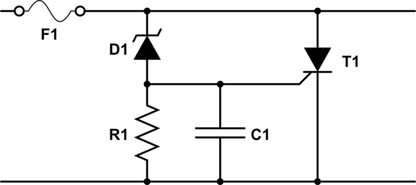
It looks something like this:
<!-- Begin schematic: In order to preserve an editable schematic, please
don't edit this section directly.
Click the "edit" link below the image in the preview instead. -->

<!-- End schematic -->
T1 is a thyristor. Normally it does not conduct. When the gate (the lead coming out the side) reaches some threshold voltage above the cathode (on the bottom), the thyristor begins conducting and won't stop until the current through the thyristor (from anode to cathode) decreases below some threshold.
When the threshold of D1 is reached, current begins to flow in R1, and consequently the voltage across R1 also increases. The thyristor's gate-cathode is in parallel with R1, so its voltage increases too. When the voltage across R1 reaches T1's threshold, T1 begins conducting and the crowbar is tripped.
C1 is just there to reduce nuisance tripping.
Two things can happen:
- the current will be very high, and blow the fuse
- the current won't be very high, and the fuse won't blow, and T1 will keep conducting until the fault is removed.
Accordingly, you'll want to select the fuse and spec the thyristor such that if the fuse doesn't blow, the thyristor won't overheat. This is easier since the voltage across a thyristor in conducting mode is relatively small.
You'll probably want to add to this arrangement a diode across the input which is normally reverse biased, but is forward biased in case the input voltage polarity is backwards. In this case the diode will conduct and either clamp the voltage to a safe level or blow the fuse.