The DC-AC inverters with schematics usually use a laminated iron transformer with a low voltage winding connected to a 50 or 60 Hz square wave circuit, and the output is from the 120 or 240 VAC winding. Because the transformer operates at such low frequency, it must be large and heavy. The advantage of such designs is their simplicity and low cost, especially if one uses a very common 12 V or 24 V center tapped transformer.
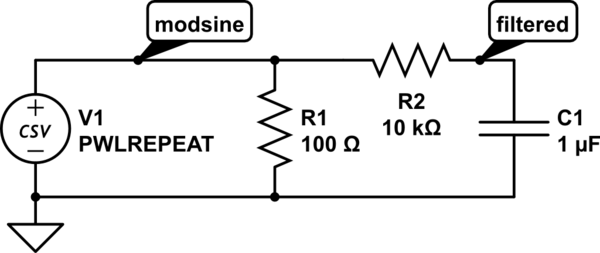
The compact automotive inverters rectify the 12 or 24 VDC input to get a nominal 15-30 VDC power bus, and a high frequency (20-50 KHz) switching circuit that uses a much smaller ferrite core step-up transformer, rectifiers, and capacitor, which produces a nominal 135 or 270 VDC bus. This is used with an H-bridge to get a "modified sine wave", consisting of rectangular pulses with an RMS value equivalent to 120 or 240 VAC mains. Waveform looks like this:
[![Modified sine wave][1]][1]
<!-- Begin schematic: In order to preserve an editable schematic, please
don't edit this section directly.
Click the "edit" link below the image in the preview instead. -->

<!-- End schematic -->
The pure sine wave inverters use variable duty cycle PWM that produces the equivalent of a sine wave. This same principle is used for industrial 3 phase variable frequency drives (VFDs), mostly to drive induction motors, in a range from about 1/2 HP (375 watts), to 50 HP (37 kW) or more. VFDs usually are designed to use 240 or 480 V three phase, but some will also work on single phase.
[1]: https://i.sstatic.net/KyKS9.png