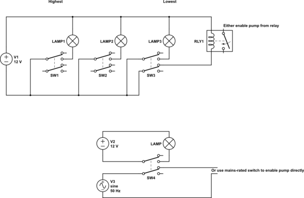
Consider something simpler made from just switches.
From each switch lever, suspend a float on a fixed length thread/light chain. When the water is high enough, the float releases the switch. When water is too low, the weight of the float activates the switch. This kind of design has the advantage that all the electrical parts are above water; also it's easy to test: you push the switches manually and make sure all your signals work as desired. (I'm not entirely sure what exact functionality you want from your ladder drawing.)
[![enter image description here][1]][1]
If you use two pole switches, you can organise your indicators completely independently of your pump lockout. You can get switches which are okay for mains. Or if you want to keep them completely isolated, you could use a relay.
<!-- Begin schematic: In order to preserve an editable schematic, please
don't edit this section directly.
Click the "edit" link below the image in the preview instead. -->

<!-- End schematic -->
Alternatively, you could use magnets with reed relays, but I'd expect the microswitch with lever and float/weight is simplest.
## Typical Switches and Floats
[![enter image description here][2]][2]
_Frm [ZF Switches](https://eu.mouser.com/datasheet/2/833/General_Purpose_E_Microswitch_Double_Pole_Datashee-3032345.pdf)_
[![enter image description here][3]][3]
_From [Plastech](http://www.hiplastech.com/product_view_24.html)_
[1]: https://i.sstatic.net/pIWF3.png
[2]: https://i.sstatic.net/C37Lc.png
[3]: https://i.sstatic.net/OC7ZW.png