> CIN, it's supposed to shunt high frequency noise.
That it does, too but it's not its primary purpose (if it was, it wouldn't be a 1µF, often done with an electrolytic cap, but something like a 100 nF ceramic capacitor).
It's stabilizing the input of the regulator: The input voltage source doesn't have zero impedance, and neither do the conductors connecting the regulator to that. Especially if any of that is inductive, a fast change in current draw by the load can result in a fast change in current draw by the regulator, which will lead to a voltage drop in Vin, which the regulator has to compensate by reducing its inner effective resistance (so that there's less voltage difference between in and out) if linear, or by drawing more current on average (higher duty cycle) if a switching regulator, but then the source catches up too late, the input voltage rises, the regulator overcompensates, and things start to wobble.
This input capacitor makes sure that transient spikes in current draw are quickly dealt with, thereby stabilizing the whole system.
> if the amplitude of the noise is 100mv then I = 1.38A. That's a ton to draw, no?
Well, that's exactly the point. The noise source wouldn't be able to supply that, so noise voltage would be lower!
Also, for transient things to come out of inductors and capacitors, it's not *that* much.
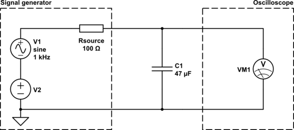
> I must be thinking about this wrong because I've also tried another experiment. I connected a signal generator with a sine wave with an amplitude of 0.1V on top of a DC 1V offset to the power rails of a breadboard. I placed a 47uF cap on the rails as well and the scope showed an almost fully attenuated signal
Check the output impedance of your signal generator! (and of your scope, too. If you can, set it to "high-Z" input mode, so that it has megaohms of input resistance. High frequency instruments often are 50Ω-terminated.)
Draw the schematic of your system including that output resistance in series to your AC+DC voltage source.
<!-- Begin schematic: In order to preserve an editable schematic, please
don't edit this section directly.
Click the "edit" link below the image in the preview instead. -->

<!-- End schematic -->
Now you've got your Rsource--C1 voltage divider. Calculate again!
Things get even uglier in reality. You'd have to add an inductor in series to Rsource, too, signifying the inductive properties of the wires and rails on your breadboard. Then, you get the voltage over C1 as voltage divider composed of (Rsource+I_parasitic) and C1.