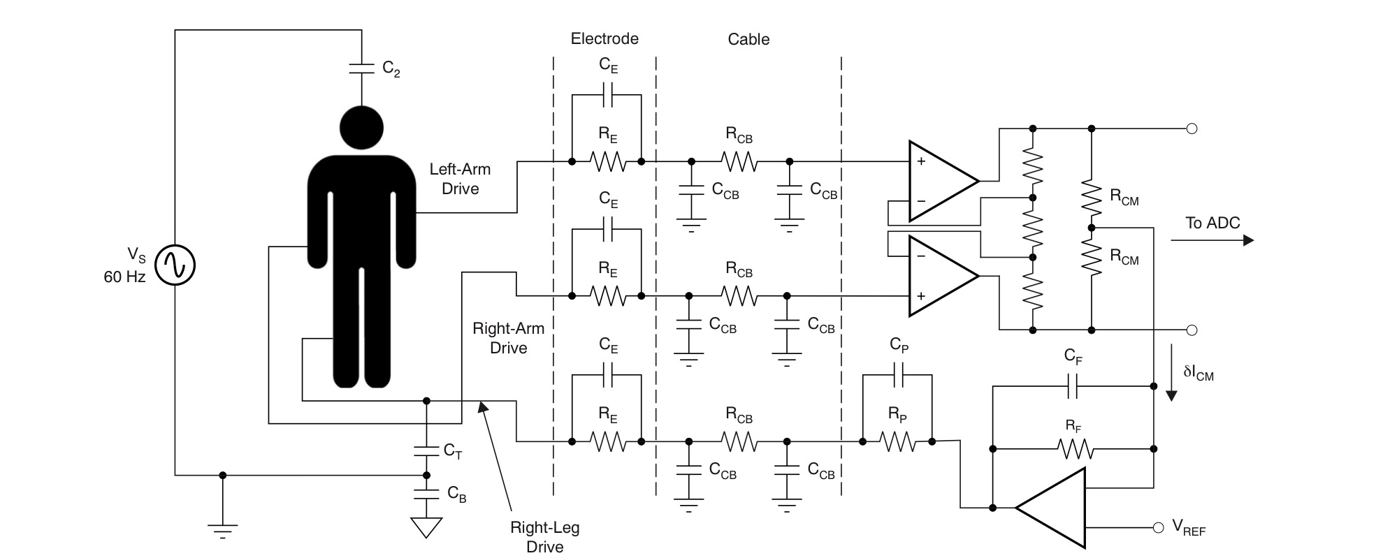
The common mode voltage of the inputs is normally established with a right leg drive amplifier output. Or a resistor to a voltage well within the common mode range of the inputs. It has to supply the total bias current of the two inputs plus any leakage (which must be very low for safety) plus AC pickup from the mains (perhaps 20V VAC through 100pF, so less than 1uA).
You do not directly use the reference pin on the inamp- it is a low impedance pin and should be connected to the circuit common or another 'stiff' voltage source in order to determine the midpoint of the inamp output voltage,
More in this TI document.
In the case of using an inamp you can draw the common mode signal by splitting the gain resistor, which isn't quite as good (see the AD620 datasheet).
Make sure you address safety issues exhaustively- your circuit should certainly not be capable of putting anything like 1mA through the victim patient, even in the case of a failure.

