How to understand diodes
========================
As with all semiconductor devices, intuitive understanding of diode circuits requires not only knowledge of semiconductor theory but also a functional understanding. We need to be able to imagine what these devices are doing in circuits to understand them.
The diode IV curve gives us the best idea of this. We can obtain it in two ways - by varying the current and measuring the voltage (V = f(I)), or by varying the voltage and measuring the current (I = f(V)). The first way is preferable because it allows obtaining more points; the second is generally accepted and can be easily implemented by the CircuitLab *DC sweep simulation* if we set the simulation step small enough.
I have shown the evolution of the diode representation by separate "shots" of the setup that correspond to some (operating) point from the IV curve.
Real diode
==========
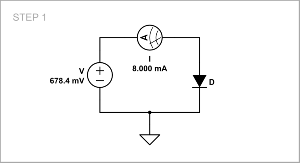
So the measuring setup is simple - a voltage source connected through an ammeter to the diode. The only thing that is required of us is to carefully change the voltage within the permissible limits (somewhere up to 0.8 V for an Si diode) so as not to exceed the maximum permissible current of the diode (for example, 100 mA).
<!-- Begin schematic: In order to preserve an editable schematic, please
don't edit this section directly.
Click the "edit" link below the image in the preview instead. -->
<!-- End schematic -->
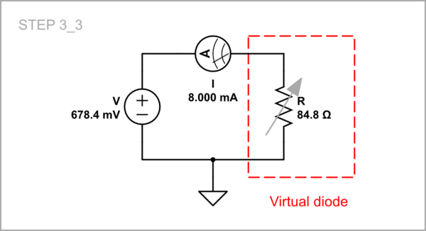
As you can see, to represent the *point 2* from the graph below in the setup, I have adjusted the voltage to 678.4 mV to cause 8 mA current flowing through the diode. In the DC sweep parameters, I have set a voltage range 0 ÷ 690 mV.
[![Diode IV curve I = f(V)_1][1]][1]
Looking at this highly non-linear curve, we want to somehow understand how the diode does it.
Virtual diodes
==========
For the purposes of intuitive understanding and calculating, we can replace (model) the more sophisticated real diode by simpler and well-known equivalent electrical devices or circuits.
"Ideal" diode and resistor
---------------------------
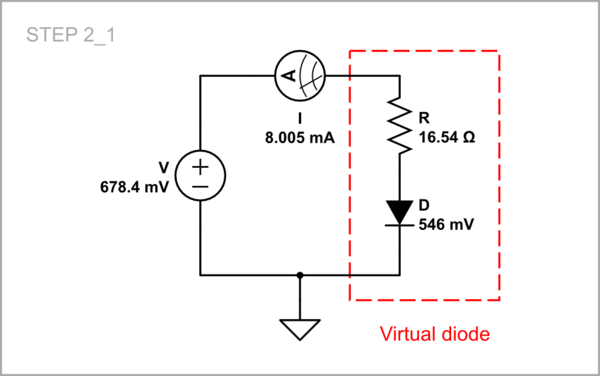
A rather crude textbook simplification is to represent the curve as assembled from two segments - horizontal and close to vertical. As they explained to me as a student in the 70's, the devices that represent them can be an "ideal" diode and a low resistance resistor in series. Back then I was unsuccessfully trying to buy an "ideal" diode from the electronics stores :-) but now I see that CircuitLab gives me the opportunity to use as many "ideal" diodes as I want for free. Let's then take one and set the values of its forward voltage (in *parameters*) and resistance R so that the circuit corresponds to point 2 in the graph above.
<!-- Begin schematic: In order to preserve an editable schematic, please
don't edit this section directly.
Click the "edit" link below the image in the preview instead. -->
<!-- End schematic -->
This is what the IV curve looks like for our simplified diode (that is how it looked in my student textbooks too).
[![Diode IV curve I = f(V)_2][2]][2]
Voltage source and resistor
---------------------------
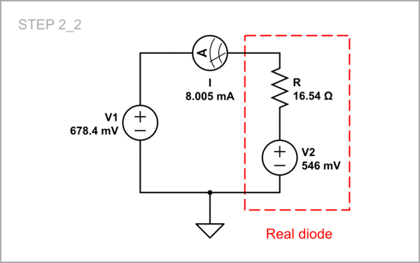
But the "ideal" diode was something quite abstract, and maybe that is why others presented the diode to me as an "ideal" voltage source and a low resistance resistor in series. This brought me new frustrations at the time because I was unsuccessfully trying to power a small radio receiver with a few diodes in series:-) But let's try it now with the help of CircuitLab.
<!-- Begin schematic: In order to preserve an editable schematic, please
don't edit this section directly.
Click the "edit" link below the image in the preview instead. -->
<!-- End schematic -->
The IV curve should look like this…
[![Diode IV curve I = f(V)_3_2][3]][3]
... but here is what the graph is. Obviously, this is not a very good model for beginners...
[![Diode IV curve I = f(V)_3_2][4]][4]
Dynamic resistor
----------
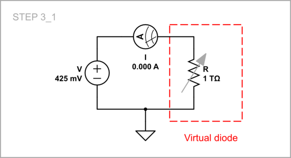
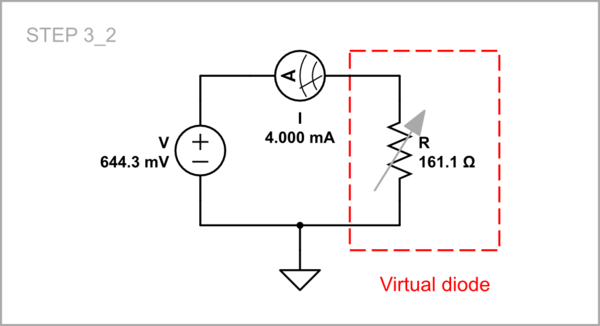
I understood what the diode actually did when I imagined it as a varying, "dynamic" resistor which varies its resistance so as to maintain a relatively constant voltage. Let's see what it is for three typical points on the curve.
**Point 0:** VF = 425 mV; IF = 0 mA, R = infinite.
<!-- Begin schematic: In order to preserve an editable schematic, please
don't edit this section directly.
Click the "edit" link below the image in the preview instead. -->
<!-- End schematic -->
[![Diode IV curve I = f(V)_5][6]][6]
**Point 1:** VF = 644.3 mV, IF = 4 mA, R = 161.1 ohm.
<!-- Begin schematic: In order to preserve an editable schematic, please
don't edit this section directly.
Click the "edit" link below the image in the preview instead. -->
<!-- End schematic -->
[![Diode IV curve I = f(V)_5][7]][7]
**Point 2:** VF = 678.4 mV, IF = 8 mA, R = 84.8 ohm.
<!-- Begin schematic: In order to preserve an editable schematic, please
don't edit this section directly.
Click the "edit" link below the image in the preview instead. -->
<!-- End schematic -->
[![Diode IV curve I = f(V)_6][8]][8]
As we can see as the voltage increases the resistance decreases and the IV curve is almost vertical.
[1]: https://i.sstatic.net/KlWWp.png
[2]: https://i.sstatic.net/KFH7K.png
[3]: https://i.sstatic.net/ty7CC.png
[4]: https://i.sstatic.net/QyAD1.png
[5]: https://i.sstatic.net/RlDCn.png
[6]: https://i.sstatic.net/lT9QP.png
[7]: https://i.sstatic.net/AN6By.png
[8]: https://i.sstatic.net/nfeDA.png