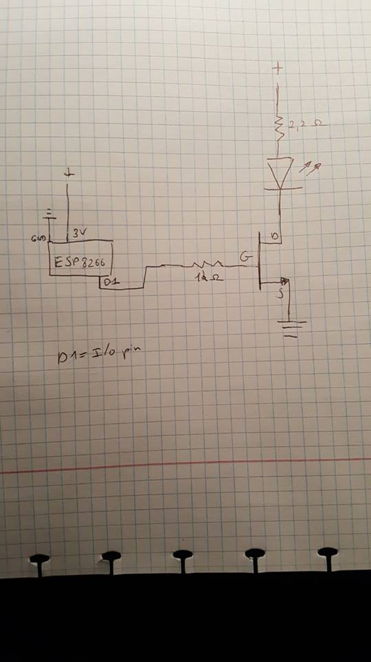
I'm building a project that uses a high power LED (3 Watt) in connection with an ESP8266 module using the module as an access point and connecting to it with my smarthpone. I've successfully managed to switch the led on and off with my smartphone and connecting the I/O pin to a logic gate MOSFET using a simple LED circuit with just a resistor and the MOSFET.
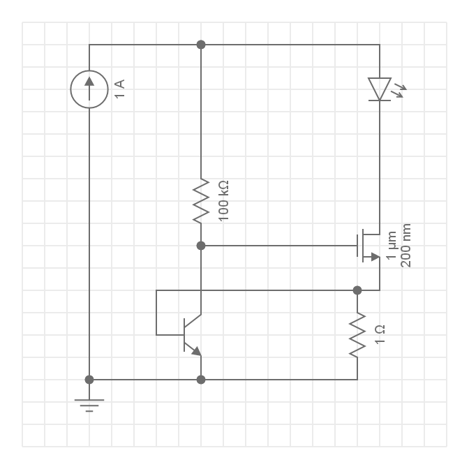
Now though I want to have a better and more efficient circuit for driving my LED and came up with this the 1A constant current supply is supposed to be a 3.7v lithion ion battery but i didn't know how to use that with the program I used to make the circuit so by no means is the current supply constant(see image) This isn't my own design, I found it online, the reason why it's better is this:
" Q2 (a power NFET) is used as a variable resistor. Q2 starts out turned on by R1.
Q1 (a small NPN) is used as an over-current sensing switch, and R3 is the "sense resistor" or "set resistor" that triggers Q1 when too much current is flowing.
The main current flow is through the LED's, through Q2, and through R3. When too much current flows through R3, Q1 will start to turn on, which starts turning off Q2. Turning off Q2 reduces the current through the LED's and R3. So we've created a "feedback loop", which continuously monitors the LED current and keeps it exactly at the set point at all times. transistors are clever, huh!
R1 has high resistance, so that when Q1 starts turning on, it easily overpowers R1.
The result is that Q2 acts like a resistor, and its resistance is always perfectly set to keep the LED current correct. Any excess power is burned in Q2. Thus for maximum efficiency, we want to configure our LED string so that it is close to the power supply voltage. It will work fine if we don't do this, we'll just waste power. this is really the only downside of this circuit compared to a step-down switching regulator!
setting the current!
the value of R3 determines the set current."
The problem now is I don't know how to use my ESP8266 again as a switch because I don't know where to connect the I/O pin where as previously I connected it to the MOSFET and basically used it as a switch but in my current circuit I don't know where to connect the I/O pin
