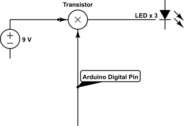
simulate this circuit – Schematic created using CircuitLab
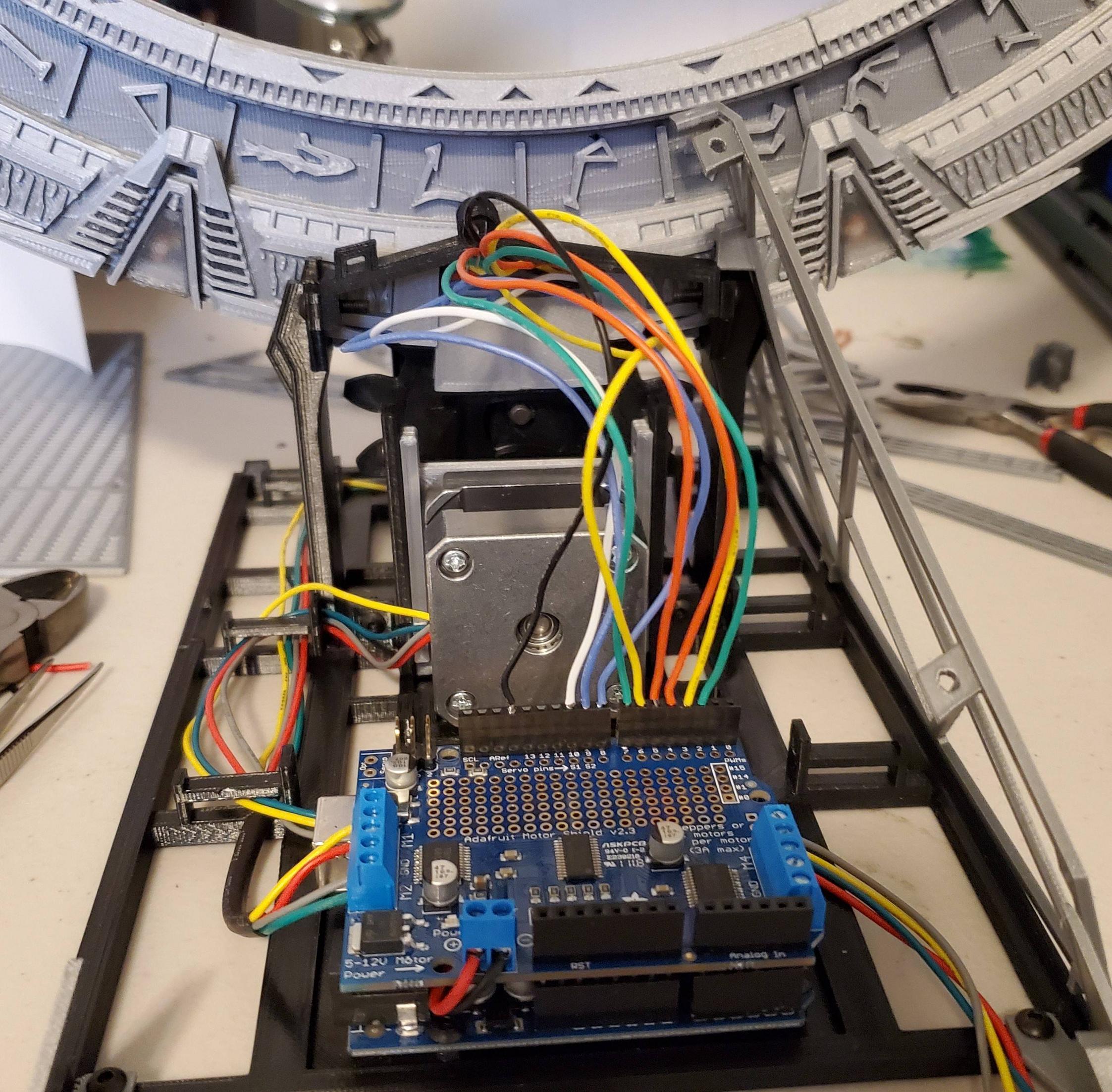
 [![enter image description here][2]][2]Kinda new to building my own electronics. I am Building a Stargate with 3d printed parts. When I soldered all the LED's together, I connected them in series (9 sets of 3 LED's) with a common ground as that is how I had seen others do it in the 3d printing community. After getting all of the soldering done, I glued the cover on it and when testing realized that in series the arduino doesn't have enough power to light the LED's completely, they do turn on but barely visible. It's too late to go pack and re-solder them in parallel since I have already glued all the plastic parts together using 3D Gloop which bonds the PLA plastic together chemically. What I need to do is provide a 9V charge to each set of 3 lights and I understand from my google searches and youtube that I can do that with transistors. All the video's and information I have seen show the transistor using the ground between the collector and emitter to regulate the flow with the base connected to the digital pin of the arduino to activate it. Since I wired all the sets of LED's to a common ground and they need to be turned on individually, I need to run the 9V through the transistors to the 9 sets of LED's individually and I'm really not sure what type of resistor to use. The LED's already have 220 ohm resistors connected inside the stargate if that helps. Any assistance would be appreciated since this is a graduation present for my nephew. Thanks
