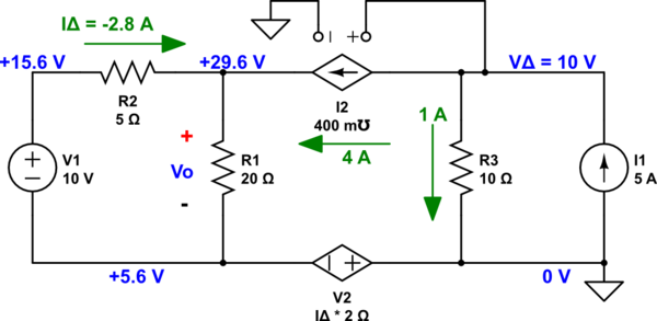
## Segue
I've already explained in comments about a point of view I could suggest that is congruent with your quoted source. But you then write:
> Won't the current from the voltage with the 2idelta' value below not
> pass through the 10 ohm resistor? And because of that we will find new
> voltage value on the right top?
Your question is apt. And it motivated me to write because the answer to your question is actually ***interesting***.
## The current in the dependent voltage source is zero
The current in the dependent voltage source, the one whose voltage is \$2\cdot i_\Delta\$, cannot be anything other than **zero** Amps. And it's obvious from the most basic inspection of the circuit.
And since you don't have part numbers in your schematic and if I don't assign them then I can't even talk to you, I am *forced* into laying out the schematic myself.
(Let this be a lesson to use the schematic editor and ***not*** to take the easy way out when asking questions by just pasting pictures.)
Here it is:
<!-- Begin schematic: In order to preserve an editable schematic, please
don't edit this section directly.
Click the "edit" link below the image in the preview instead. -->

<!-- End schematic -->
You can trivially determine that the current in \$V_2\$ must be zero. An ideal current source has an impedance magnitude of \$\infty\$. And \$I_2\$ is such a source. As such and because \$I_2\$ depends entirely on the voltage across \$R_3\$, it's simply not possible for there to be anything other than zero current in \$V_2\$.
If you need a mathematical approach to convince you, then all you need to do is assign ground as shown here:
<!-- Begin schematic: In order to preserve an editable schematic, please
don't edit this section directly.
Click the "edit" link below the image in the preview instead. -->

<!-- End schematic -->
Look at the KCL for \$V_\Delta\$: \$\frac{V_\Delta}{R_3} + 0.4\:\mho\cdot V_\Delta= 5\:\text{A}\$. This instantly solves out to \$V_\Delta=10\:\text{V}\$.
There is \$1\:\text{A}\$ in \$R_3\$ and all the rest **must** be going out through \$I_2\$. And there is ***no room*** for the addition of ***any*** current through \$V_2\$. Everything is already determined by \$I_1\$, \$I_2\$, and \$R_3\$. And nothing can be changed there.
It won't matter ***where*** you put ground, either. None of this changes the above conclusion, which remains no matter how you look at the circuit.
There simply cannot be any current in \$V_2\$. It's not possible. So in answer to your question in the segue, there's no current in \$V_2\$. End of story. Done.
## So where does this leave us?
We can now reduce the circuit further:
<!-- Begin schematic: In order to preserve an editable schematic, please
don't edit this section directly.
Click the "edit" link below the image in the preview instead. -->

<!-- End schematic -->
This solves out trivially to \$V_\Delta=24\:\text{V}\$, \$I_\Delta=-2.8\:\text{A}\$, and \$V_{\Delta\text{( - )}}=-5.6\:\text{V}\$.
Plugging all this back into the original schematic, and keeping the original ground reference that I earlier added, we find:
<!-- Begin schematic: In order to preserve an editable schematic, please
don't edit this section directly.
Click the "edit" link below the image in the preview instead. -->

<!-- End schematic -->
You are free to choose a different ground reference. But it won't change the currents in any way or the voltage differences between the nodes.