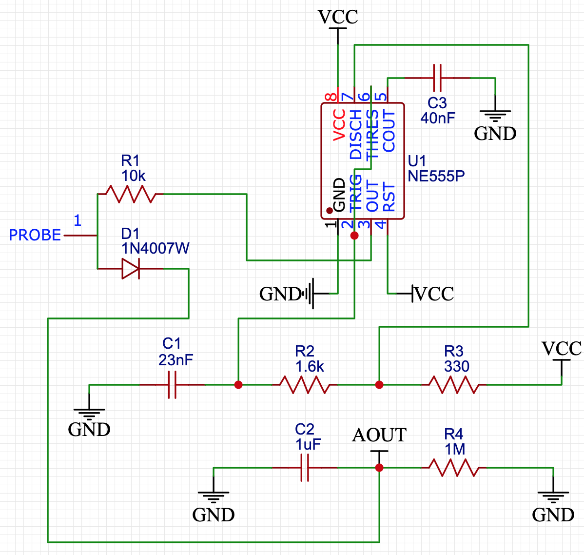
I have spent the past few days trying to reverse engineer a capacitive moisture sensor I ordered from eBay a while ago (https://www.ebay.de/itm/5X-NEW-Analog-Capacitive-Soil-Moisture-Sensor-Corrosion-Resistant-With-Cable-/264156193308?_trksid=p2385738.m4383.l4275.c10). What fascinated me about this sensor was that I could put it in a plastic bag and it would still be able to give accurate moisture readings. In air, the output voltage of the sensor is about 2.3v; in water, I am getting around 0.7v when submerged directly and 1.6v when submerged in a plastic bag. After analysing the circuit, I came up with this schematic:
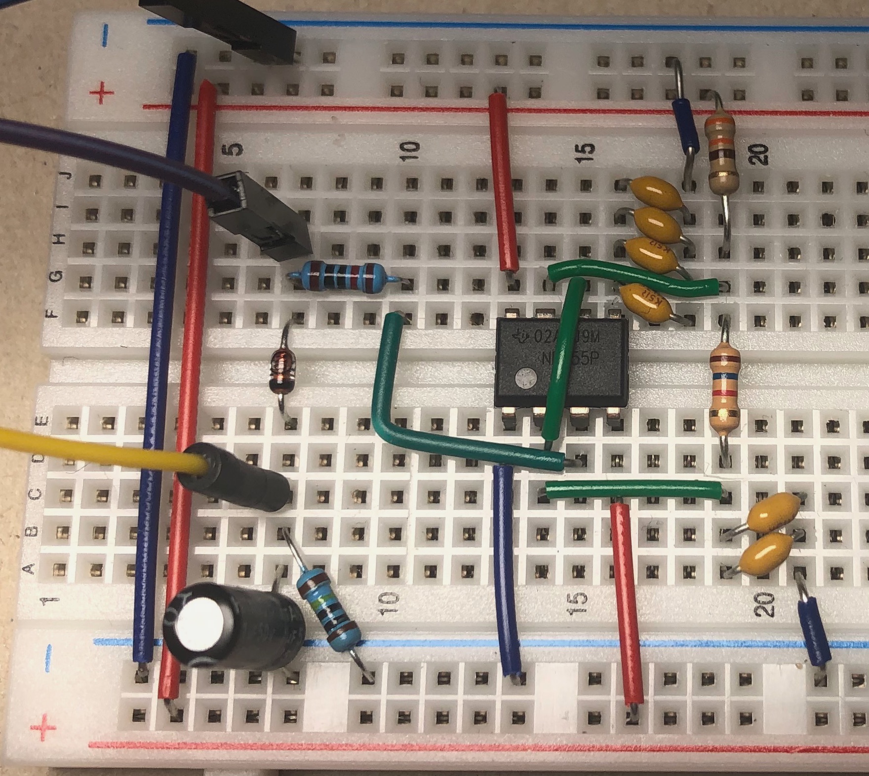
I then build a prototype on a breadboard, which gave me this result:
Unfortunately, my sensor does not work as well as the one I bought, because the voltage drops seem to be a lot smaller. The output voltage in the air is the same. But when submerging it directly in water, I am getting 1.6v (as opposed to 0.7v for the bought one). When submerging it in a plastic bag, I can only see a voltage drop of 10mv to about 2.29v.
I have already re-measured the component values several times and also buzzed out all the traces again to make sure I got the connections right, but I obviously must be missing something. One thing I have noticed while testing is that decreasing the value of C1 from 23nF to something like 470pF causes larger voltage drops, which makes my custom built sensor behave more like the bought one. But I'm still far from what I would like to see.
I'm an electronics beginner and this is one of my first reverse engineering projects, so any advice/tip would be greatly appreciated.


