On editing your question, I see that what you really want to do is to switch the LEDs from a microprocessor output.
The easiest way to do that is in your program. Use two GPIOs, and always switch one off when the other is on.
If you can't change the program, then you could do something like this:

simulate this circuit – Schematic created using CircuitLab
That turns the green LED on when the GPIO is high, and it turns the red LED on when the GPIO is low. Only one or the other will be on, never both.
Original answer:
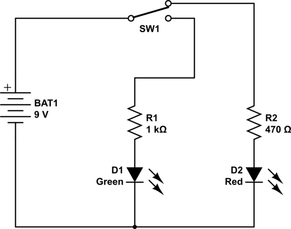
What you need is a single pole double throw (SPDT) switch.
The circuit looks like this:

One LED will always be turned on.
The resistors are not optional. You must have them to keep the LEDs from burning out. There are plenty of posts on this site about calculating the resistor values given the battery voltage, the LED forward voltage, and the LED current - I'm not going to go into that here.
The resistors are useful for a second reason, as well.
Red and green LEDs don't light equally bright for the same current. With separate resistors, you can tweak the current to make the LEDs approximately equally bright.
