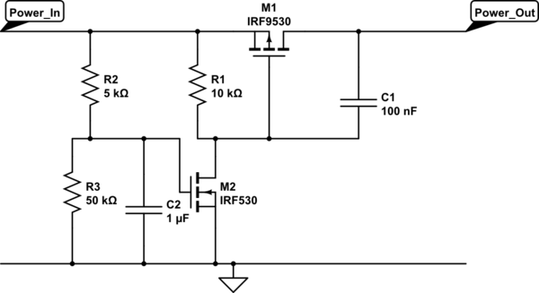
A quick and simple way of switching the power to the Pi on is simple enough.
<!-- Begin schematic: In order to preserve an editable schematic, please
don't edit this section directly.
Click the "edit" link below the image in the preview instead. -->

<!-- End schematic -->
The turn on is controlled by C2 charging through R2/R3 until it hits the threshold voltage of M2. It's a little crude and may require a little playing with values depending on the exact parts used but it does give you a basic minimum voltage and time delay on the switch on.
When M2 turns on it pulls the gate of M1 low and turns on the power output to the Pi. C1 is optional and provides a soft start to the power output, it ramps the voltage up rather than switching as quickly as possible and risking pulling the input voltage down if the supply can't cope with the sudden change in demand.
Any low voltage N channel will work for M2, the threshold voltage of the part will determine the ratio needed for R2 and R3. The time delay after crossing the input threshold before turning on will determine the absolute values for R2,R3 and C2.
M1 should have a threshold voltage of around -3V or less (assuming you're controlling the 5V rail) and be able to cope with the current draw of the Pi or whatever else it is controlling the power to.
If you can get the parts easily then replace M2, C2, R2 & R3 with a dedicated power on reset device. These are designed to hold a part in reset until a few milliseconds after the supply voltage has crossed a minimum voltage threshold. That would provide a cleaner way to drive the gate of M1.
Having said that you probably don't have anything to worry about, any in car USB adapter should be designed to cope with the mess that passes for a power supply in a car. It doesn't matter how nasty your 12V supply is, in comparison to a car it will be very low noise.