I've built a flyback transformer by hand for a circuit I am making and after shorting the secondary I have found my leakage inductance is very high. The primary inductance is around 2 mH, while the leakage inductance is at 1.3 mH and it is supposed to be at max only 60 uH. I have made the transformer twice now with the same result and I can't figure out what is going on.
Primary turns: 143
Secondary turns: 6 trifilar
As requested I am providing more detail. My primary inductance is calculated by:
$$ Lp = Vin^20.5*Duty*eff/(Po*fs) $$
Vin = 135V, Duty=0.636, eff=0.72, Po = 10W, fs =137kHz
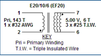
I need to have a target primary inductanced around 1900-2000 uH, and so I need to used a gapped core. The transformer construction given by PI designer is. Note there are 3 layers of tape between primary and secondary.
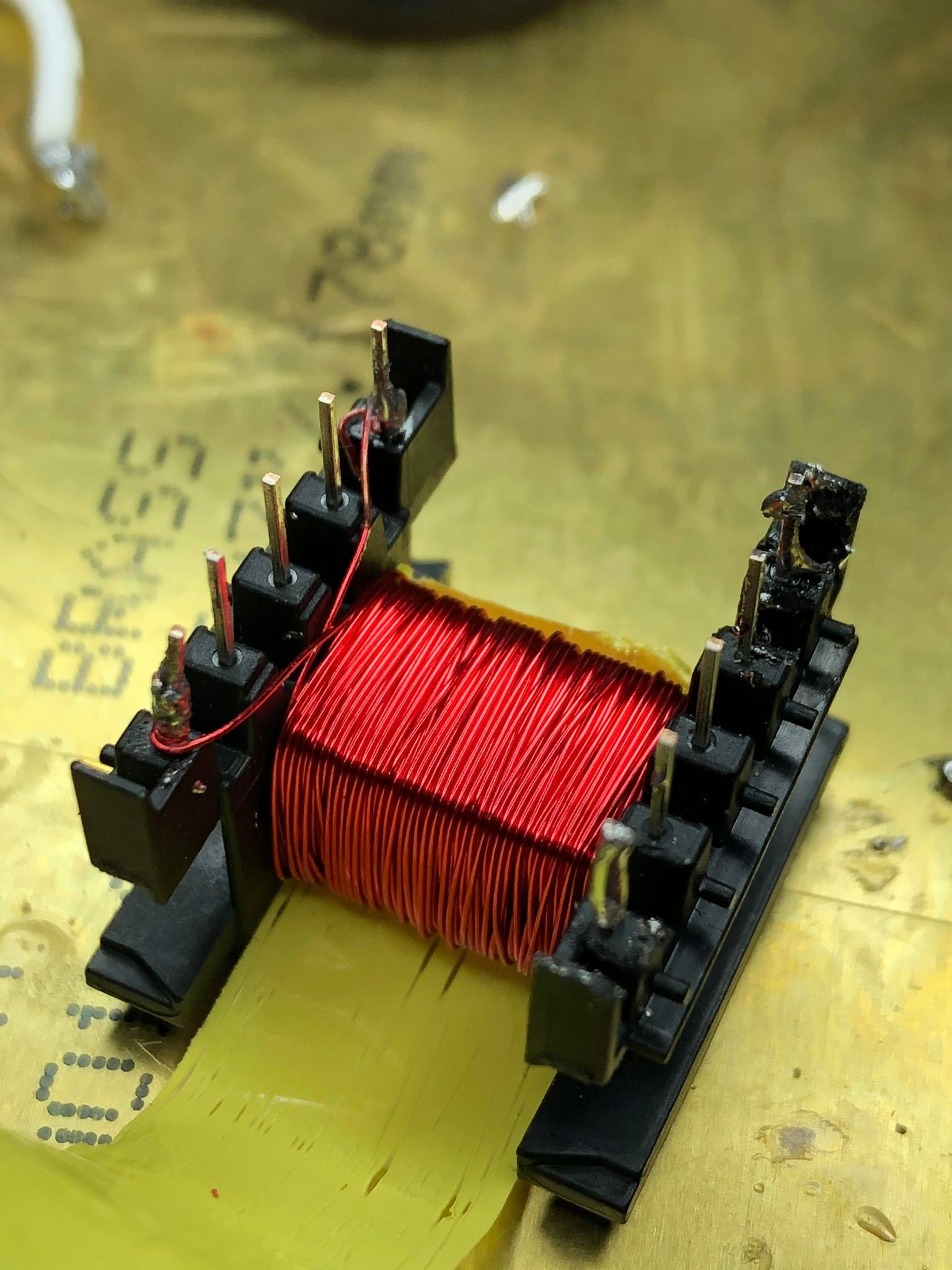
My Primary winding looks like this:

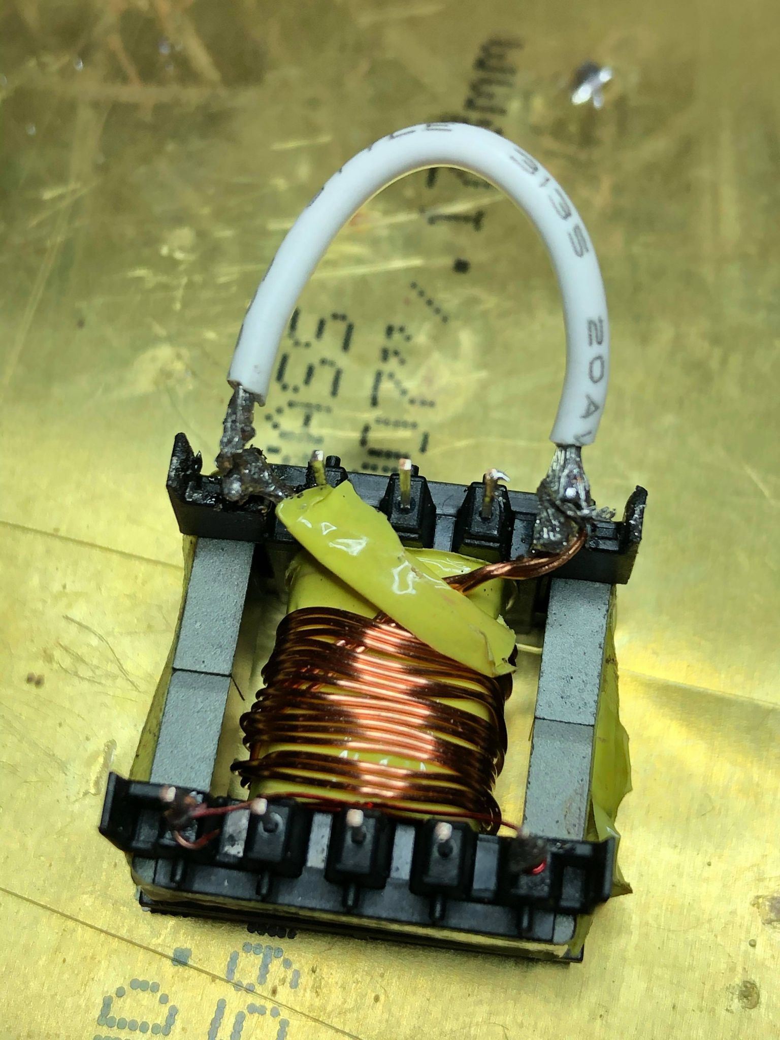
Shorted secondary to measure leakage:

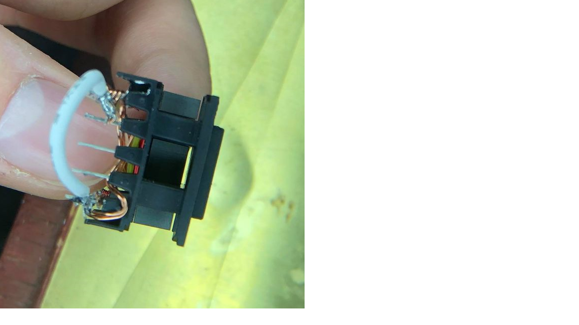
Picture of core inside bobbin, there is a slight gap at the top which could potentially contribute:

The core material I am using is N27, core is gapped 0.17MM (recommended core gap from PI is 1.2 mm. Here is the data sheet

