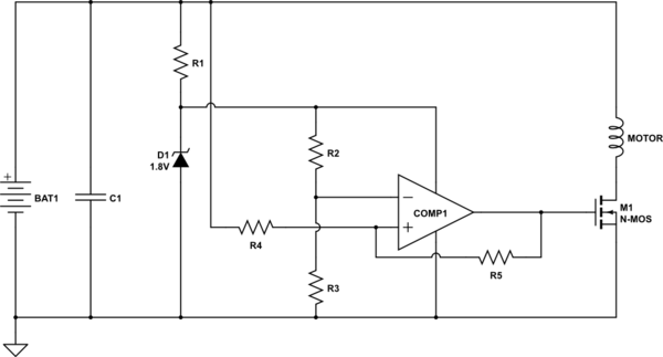
Not having full your full requirements, it's hard to do a precise design.
But basically, you need 2 things :
1) an electronic "switch" : that would be some kind of transistor (probably either bipolar or mosfet)
2) a circuit telling you when you get enough voltage in the capacitor and when you have to stop emptying it because the voltage is too low (no point to keep using up energy once the voltage is too low to keep the motor spining). So I would say some kind of comparator with hysteresis.
So some idea would be the following :
<!-- Begin schematic: In order to preserve an editable schematic, please
don't edit this section directly.
Click the "edit" link below the image in the preview instead. -->

<!-- End schematic -->
COMP1 is a comparator (if you don't know them, its a bit like an Op-Amp without negative feedback, but optimized for it). Depending on the model, you might need to add a pull-up resistor to the output.
Note that all resistors will need to have huge resistance, or you will consume too much power. I guess that you will use no resistor bellow 100k.
D1 and R1 provide a stable supply voltage to the comparator (if D1 is a 1.8V zener, then the supply voltage is 1.8V). Make sure to use a big resistor for R1 in order to avoid waisting your precious energy. Note that this is an OK solution only because the comparator draws very very little current.
The comparator COMP1 and R2 to R5 form an non inverting comparator with histeresis. This means that when the voltage of the capacitor rises above Vth+, then the output goes high. If it falls bellow a different threshold Vth-, the output goes low. Vth+>Vth-. For example, if you choose your resistors for Vth+=3V and Vth-=2V, then the motor will turn on when the capacitor reaches 3V, and go out when it emptied at 2V (without hysteresis, you have a single threshold, so the motor would oscillate quickly between on and off).
The N-MOS M1 will act as a closed switch if the voltage at its input (gate) is greater than some threshold. Note that 1.8V is quite low for a MOSFET, so you have to carefully pick one that turns on at such low voltage. Alternatively, you can use a bipolar transistor, but it will waist some energy.
A few extra notes :
- you probably want a free-wheeling diode to protect the mosfet when you switch off
- I'm not really sure how this will behave if you get less voltage than the minimal working voltage of the comparator. So maybe still get a switch just after the capacitor, excepted that now, you only switch it on once at the beginning, and then everything keeps going by itself
Let me know if you need help to dig further (in that case, I will need full specification of your needs : voltage at which to switch on/off the motor, current produced by the cell, current consumed by the motor, and some idea about your level in electronics to adapt my explanations)