Since you asked me to expand on my earlier comment: ...
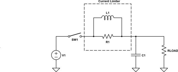
In the olden days, we used *heavy iron* a lot for handling inrush currents -- **big** inductors. A resistor was often added in parallel to the heavy inductor and the pair was used in series between the power source and the capacitor bank. Something like this:
<!-- Begin schematic: In order to preserve an editable schematic, please
don't edit this section directly.
Click the "edit" link below the image in the preview instead. -->

<!-- End schematic -->
The peak current in the resistor, \$R_1\$, will happen when the capacitance is discharged. So \$I_{R_{_\text{PEAK}}}=\frac{V_1}{R_1}\$. And that means we can select \$R_1\$ based upon what we want the peak current in the resistor to be.
Let's compute that one right now. I'm going to pick \$I_{R_{_\text{PEAK}}}=4\:\text{A}\$. This seems like a safe margin vs your relay's current limit.
**Note:** Now, pause. There will also be an increasing inductor current. And perhaps this limit isn't good enough. But in practice it will be. The reason is that while the inductor's current is climbing, so also is the limit-resistor's current declining. Done right, these will just almost perfectly cancel each other out so that if we design each for the same current limit, then the sum of their currents will also be similarly limited.
So let's work out that \$R_1=\frac{24\:\text{V}}{4\:\text{A}}=6\:\Omega\$ and choose either \$R_1=5.6\:\Omega\$ or \$R_1=6.8\:\Omega\$. I'm going to lean towards the safer side, so I'll select \$R_1=6.8\:\Omega\$. This means my new current limit will be about \$3.5\:\text{A}\$ when working out the inductance.
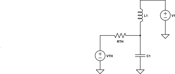
Which brings us to the inductor. To deal with the question about the peak current in the inductor, I'll re-draw the above in a slightly different, but equivalent, form:
<!-- Begin schematic: In order to preserve an editable schematic, please
don't edit this section directly.
Click the "edit" link below the image in the preview instead. -->

<!-- End schematic -->
In the above, I've "noticed" that \$R_1\$ and \$R_{_\text{LOAD}}\$ make up a voltage divider with an equivalent source voltage of \$V_{_\text{TH}}=V_1\cdot\frac{R_{_\text{LOAD}}}{R_1+R_{_\text{LOAD}}}\$ and \$R_{_\text{TH}}=R_1\cdot\frac{R_{_\text{LOAD}}}{R_1+R_{_\text{LOAD}}}\$.
What's really nice about the new arrangement is that it is easier to see it is an RLC circuit. The general idea here is that the peak inductor current happens in the first quarter of a period of time that is determined by a combination of these three items.
Roughly, you can compute \$L_1\approx \frac{16}{\pi^2}\cdot R_{_\text{TH}}^{\,^2}\cdot C_1\$. And since \$R_{_\text{TH}}=\frac{V_1}{I_{_\text{LOAD}}+I_{R_{_\text{PEAK}}}}\$, this is works out to: \$L_1\approx \frac{16}{\pi^2}\cdot C_1\cdot \left[\frac{V_1}{I_{_\text{LOAD}}+I_{R_{_\text{PEAK}}}}\right]^{\,^2}\$. Assuming \$V_1=24\:\text{V}\$, \$I_{_\text{LOAD}}=2\:\text{A}\$, and \$I_{R_{_\text{PEAK}}}=3.5\:\text{A}\$ (the new value), then \$L_1\approx 1.62\cdot 10\:\text{mF}\cdot \left[\frac{24\:\text{V}}{2\:\text{A}+3.5\:\text{A}}\right]^2=309\:\text{mH}\$. I'd pick \$L_1=270\:\text{mH}\$ as a very close, available value. (Of course, you might just as well pick \$L_1=330\:\text{mH}\$, too.)
I've no clue what's going to happen when I pop this into LTspice. (I'm going to cheat just a little bit to keep the schematic simple, as I'll have LTspice "turn on" the power supply on its own by checking off a box.) So let's see:
[![enter image description here][1]][1]
(Click on the above picture to see more detail.)
Here you can see the behavior resulting from the above approach. It's almost exactly as expected. You can see that the sum (the red curve) that is being delivered through the relay only slightly peaks over \$4\:\text{A}\$. So we have kept to our limit. But this also tells you that there will be a little more current than you target in the design, due to the fact that both the resistor and the inductor are supplying current during the early quarter-cycle (damped) phase. (Had I decided to round up and use \$L_1=330\:\text{mH}\$, then the peak current through the relay would have been about \$3.8\:\text{A}\$.)
And yes, the output voltage did ring a bit. It reached a slightly higher voltage than \$24\:\text{V}\$. Back in the day, that was fine. We were using diodes the size of your fist (selenium rectifiers with lots and lots of fins) and vacuum tubes. A little extra voltage never hurt anyone. ;) Today, you have to think about that more.
If you can accept a higher peak voltage and a higher peak inductor current, you can reduce its magnitude. Say, by half or so. If the peak voltage is critical and you cannot accept a high value, then you need to increase its magnitude. Matching up the current limit of the inductor with the current limit of the resistor usually gives the better response, though, and is a nice balance for the design.
Anyway, that's a way of doing it. The way it once was done.
Oh, and a last thought. The current-limit resistor's peak heating will all take place in the first tenth of a second. It might absorb several Joules during that turn-on period. Some resistors are better than others at handling these stresses. You can look for "surge resistors" or else wire-wound (which can handle this kind of thing well.) And definitely read the datasheets, where possible, to make sure. If the datasheet rates the resistor for a surge or a certain number of Joules in a short period, then that's likely a good thing. Finally, do some testing, as well.
[1]: https://i.sstatic.net/NwEYu.png