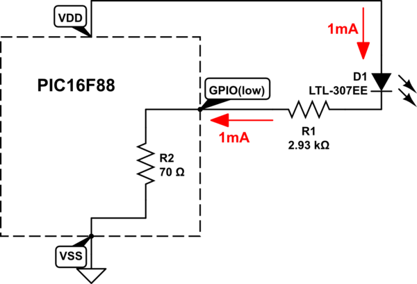
Your LED design approach is generally correct.<br>
A LED data sheet might suggest 20mA current is a maximum value. A modern, efficient LED is very bright with 20mA. In darkness, with dark-adapted eyes, you might be able to see the LED begin to glow with 0.05 mA.<br>
A rough design current for an efficient LED might be around 1 mA...that won't stress the PIC's I/O pin. 20mA is requiring the I/O pin to work rather hard.<br>
Microchip's data sheet for PIC16F88 shows the DC specifications that set some limits on GPIO (input/output) pin voltages and currents (a portion snipped below). The pertinent part is \$V_{OL}, V_{OH}\$ for **I/O ports**:<br>
[![portion of Microchip 16F88 data sheet][1]][1]
<br> It appears that an I/O pin can sink current (8.5mA) with less stress than it can supply current (1.6mA). These are not *limits*, but are a single data point within the maximum limits stated elsewhere (Section 18.0 states that maximum current on any one I/O pin shouldn't exceed 25mA).<br>
Sinking-better-than-sourcing is a common trait of GPIO output pins. So you're better off to sink...that means lighting up a LED by pulling current to ground - the LED's anode is attached to the +5V DC supply, and the GPIO pin pulls it **ON** by switching from logic **high** to logic **low**, through a series-connected resistor.<br>
Example design:<br>
A LED (when lit) requires about 2V when 1mA flows. Look to the LED's data sheet.<br>
The PIC is powered from a +5v supply, which is also the point from which the LED anode draws its current. So **VDD** is +5v compared to **VSS** at zero volts.<br>
A GPIO pin is set as "OUTPUT" and is pulled to logic **LOW** to turn on the LED.<br>
The series resistance for 1mA LED current would be \$ (5.0 - 2.0)\over (.001)\$. That's 3000 ohms.<br>
A more exact solution might account for the internal ON resistance of the PIC's I/O pin. This would be the ON-resistance of a N-channel MOSfet.<br>
The data sheet (above) suggests this resistance is \${0.6V}\over{8.5mA}\$, about 71 ohms.<br>
So a proper series resistor would be \$ 3000 - 71\$ ohms. But you wouldn't notice the difference in LED brightness compared to a 3000 ohm resistor.<br>
<!-- Begin schematic: In order to preserve an editable schematic, please
don't edit this section directly.
Click the "edit" link below the image in the preview instead. -->

<!-- End schematic -->
<br> Note that a blue LED requires more voltage to light up than a RED LED, perhaps 3.4V instead of 2.0V....*NO* current flows until you exceed a LED's turn-on voltage. It is **current** that produces light. If your DC supply was low (perhaps 3.3V), the blue LED could not be reliably lit.
> Well, how much current does an IC draw? How much is too little, how
> much is too much?
The PIC itself will draw current from its DC supply just to operate. Current flow depends a great deal on how fast it is operating...the data sheet can be confusing and has many charts showing current pulled from the DC supply under many operating conditions. While asleep, with no clocks running, it may pull a few microamps. A fast clock (20 MHz) with +5V supply might pull 5mA.<br>
In the example circuit with LED **ON**, and a 20MHz clock, 5mA might enter VDD pin. This current would also exit VSS pin. But the VSS pin would also include the 1mA LED current, so 6mA exits VSS. From the power supply, 6mA flows.<br>
Data sheet section 18.0 shows maximum limits. These are pain-of-death limits. For VDD, VSS, the limit is 200mA. That'd be one very hot PIC!. How could so much current flow? If you tried to light up many LEDS very brightly with all the available GPIO pins, with small-value series resistors (like zero ohms), a great deal of current might try to flow.<br>
*A caution regarding GPIO pins.* They default to *input* rather than *output*. A GPIO pin can float around at any voltage between VDD and VSS. The electric field of a hand waving over the chip can change its voltage. It is not good to have a GPIO pin float near half-way between VDD-VSS. Excess current can flow. An unconnected input pin should be dragged down to VSS or dragged up to VDD. Dragging might be done with a resistor, in case the pin gets set to "output".
[1]: https://i.sstatic.net/hn9Ov.png