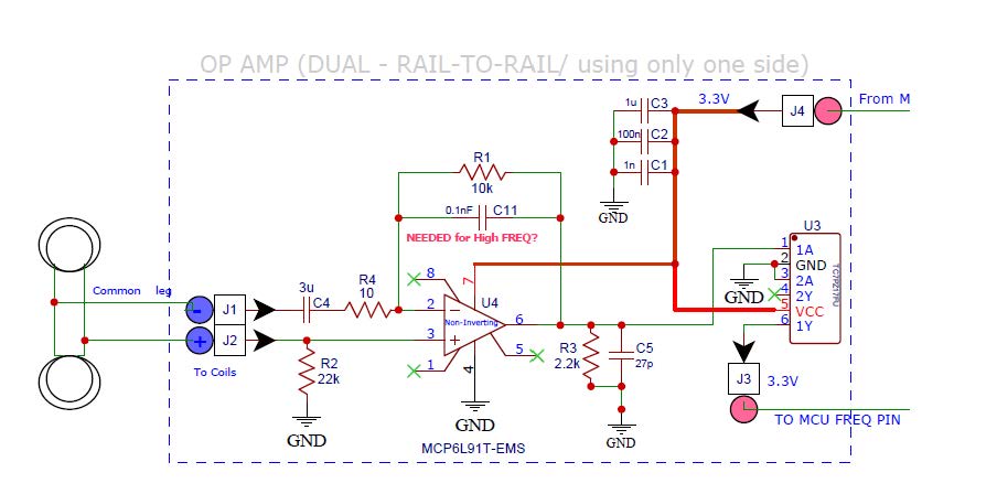
The problem is only in the input stage of the op-amp.
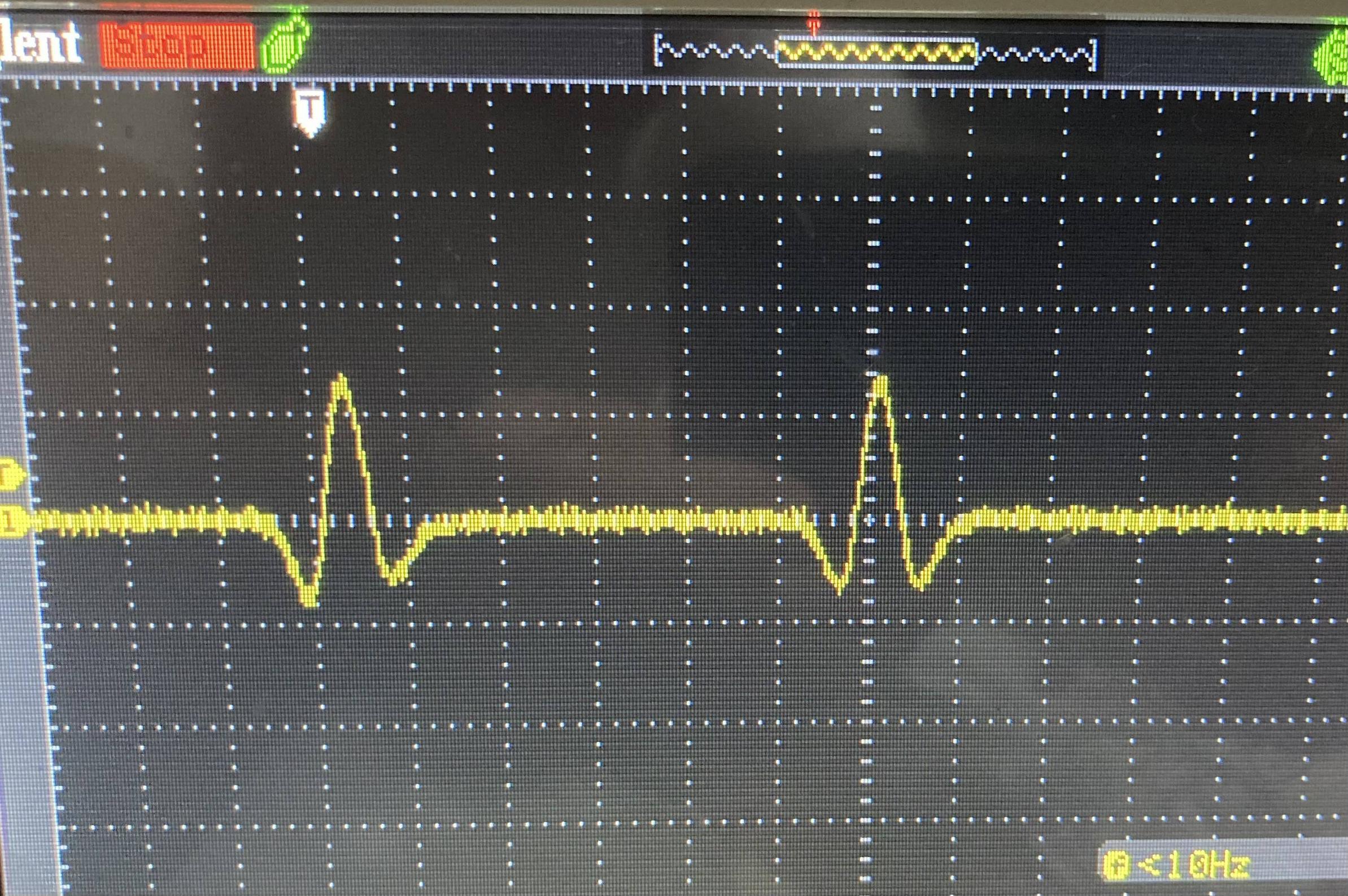
The eddy-current is generated from two coils by ferrous movement passing through them. The coils are 10 ohm each with 0.254 mH. The eddy-current coming out of them is a sine wave that goes positive and negative. The circuit works 95% of the time as it is, but at times it seems that the difference between the two op-amp inputs (2 and 3) is not enough to result in an output.
On the bench, if I simulate things and feed a positive 3 V pulse into J1 going to Pin 2 of the op-amp and also ground J2 (going to pin 3) then it works 100% of the time. Of course, in real life the eddy-current is not only positive.
I suspect that when the positive and negative eddy-current is generated in the form of a sine wave, at times the input via J2 going into pin 3 of the op-amp overrides J1 going into Pin 2 of the op-amp, thus the op-amp does not put out any amplified signals. Should I change R2 to a lower value like 2-3k, or should I add also a capacitor in series between J2 and pin 3 of the op-amp?


