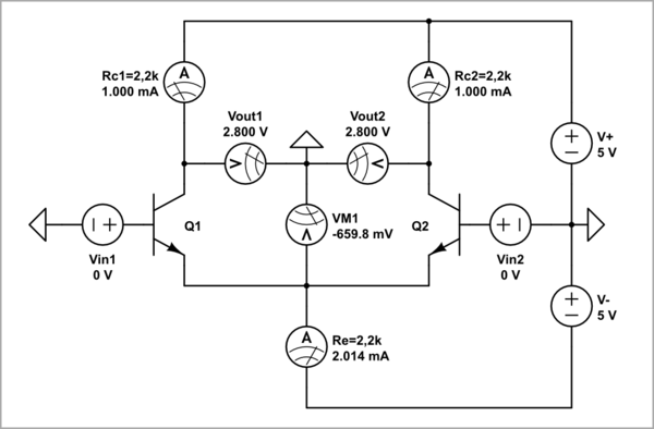
I have illustrated your question by a little unusual CircuitLab simulation consisting only of voltage sources and meters. My idea was to visualize the most important electrical quantities without cluttering the schematic. For this purpose, I have presented the collector resistors as ammeters with an internal resistance of 2.2 kΩ, and the emitter resistor - through a voltmeter with an internal resistance of 2 kΩ. Simply put, think of them as "visualized resistors".

simulate this circuit – Schematic created using CircuitLab
