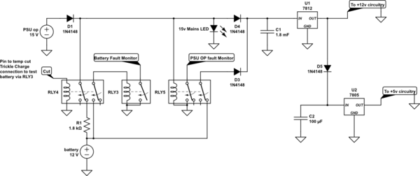
Please could somebody review my following schematic, as it is my first attempt at a PSU circuit. The aim of this circuit is as follows:
I am using a 15V (150W) PSU to power an Arduino, 2 separate 12V circuits and trickle (float) charge a 7Ah SLA battery which takes over in event of mains failure. It should also be able to monitor the mains (PSU) supply via an Arduino pin and also check the battery is OK periodically.
Regarding the charging, there is a current-limiting resistor of 1k8 to provide 0.7Ah to the battery.
Regarding the monitoring, the PSU has a 12V relay (15V applied to coil is OK) in parallel to switch a contact from/to Ground, so I can monitor the Arduino pin to see if it is reading ground or not (PSU output is OK or not).
The current-limiting resistor is also connected via a 5V relay (controlled by Arduino pin) so when the Arduino pin is switched, the current-limiting resistor is no longer in the circuit. During this time while there is no trickle charge, if the battery is OK (suitable voltage present) another relay will be energised by the battery voltage which switches another Arduino pin to ground.
I have a voltage regulator to provide 12V to the parts that need 12V and another voltage regulator to provide 5V to the Arduino (building Arduino from components).
I've attached a picture of the schematic. If someone more experienced could have a quick look and tell me if it's OK or not (and if so where) that would be great, as I know battery charging done wrongly can have pretty nasty results...
The high current from the PSU is needed to run several more Arduinos at the end of an RS485 line, as well as some addressable RGB LEDs and some other 12V components.
The battery monitoring doesn't have to indicate charge or condition, just whether it is connected and have enough voltage to run things for at least a few seconds (so it can log it) preferably longer as required, but not essential.
Thanks in advance.
***EDIT:*** changed 2 relays to DPDT which will mean when the mains is on and the battery is not being tested the battery has no load. Also added a capacitor to cope with PSU/battery switchover (during relay operation)
<!-- Begin schematic: In order to preserve an editable schematic, please
don't edit this section directly.
Click the "edit" link below the image in the preview instead. -->

<!-- End schematic -->
*OP's schematic tidied up by @Transistor.*
***EDIT:*** *Updated schematic to indicate 12v and 5v outputs and switched the erroneous wiring of the capacitor C1 to parallel (non-blocking)*
From Battery manufacturers [spec sheet][1]:
>**Charge Current**
>
>Float charge current limit (A): No limit
>
>Cyclic (or Boost) charge current limit (A): 1.75
From [powerstream.com][2]
>Sealed lead acid batteries can recycle the generated gasses as long as they are being overcharged at less than C/3.
From [mpoweruk.com][3]
>Trickle charging is designed to compensate for the self discharge of the battery. Continuous charge. Long term constant current charging for standby use.
[1]: https://www.yuasa.co.uk/yuasa/datasheet/index/sku/NP7-12FR/
[2]: https://www.powerstream.com/SLA.htm
[3]: https://www.mpoweruk.com/chargers.htm