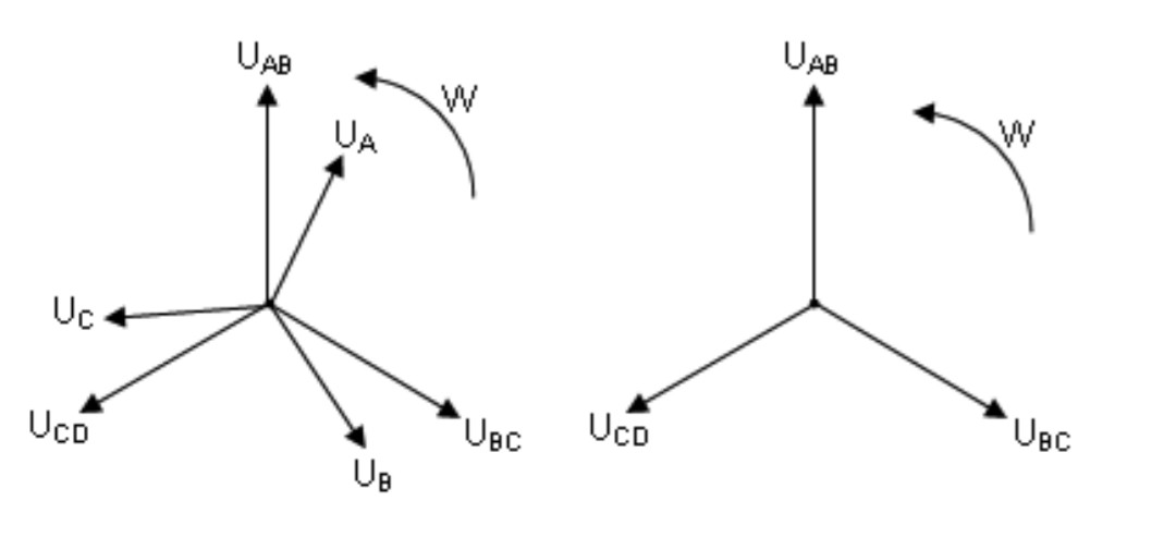
Second this week... But was it easy I wouldn't be here... **A problem asked me to identify the diagrams from this picture:**  The following are the **correct answers**, acording to the test developers. **a.** The first diagram may represent the voltage over the load of a 4-wire **Unbalanced** **Star**. **b.** The first diagram may represent the voltage over the load of a 3-wire **Balanced** **Star**. **c.** The second diagram may represent the voltage over the load of a 3-wire **Balanced** **Star**. **d.** The second diagram may represent the voltage over the load of an **Unbalanced** **Delta** Again: all the above assertions are to be taken as true --------------------------------------------------------------------------------------- **I need help understanding these truths/assertions.** --------------------------------------------------------------------------------------- - As far as I know, the line voltage is 30 degrees ahead of the phase voltage on a star connection (a neutral wire enforces this in case one of the impedances is not equal) This knowledge matches the **a.** and **b.**, but doesn't seem to my eyes to make sense for **c.**. How is the assertion **c.** possible ? - As far as I know, the line and phase voltages on deltas are equal, with No angle between them. But that wouldn't match assertion **d.** How is such assertion possible ? Maybe the trick is in the distinction between _load_ and _source_... Who has the patience for this ? If I think any longer I lose my sanity This is an adaptation of the actual question. The original is longer and not in english. I may share if requested. *I believe the D letter in the diagram is a typo