Your circuit is able to switch load current on and off very well, since the MOSFET is behaving like an open or closed switch. If you were to plot current \$I_L\$ through the load, be it a motor, a LED or a resistor, that plot would show a nice clean zero-level, alternating between 0A and some maximum.
This does not necessarily mean that load *voltage* \$V_L\$ would also be clean and rectangular, alternating between 0V and +12V, though. \$V_L\$ across a resistive load \$R\$ would indeed appear rectangular, oscillating between 0V and +12V, because \$V_L=I_LR\$. For a resistor, you would expect that when current is cut off (MOSFET off) then \$I_L=0A\$ and so \$V_L=0V\$.
I should point out that what you are measuring on your 'scope is drain potential \$V_D\$ where:
$$ V_D=(+12V) - V_L $$
Voltage across a motor is a different story, because it is rotating and generating an EMF \$V_L\$ roughly proportional to its angular velocity, ***even though current \$I_L\$ is zero***. This is manifest in your plots as \$V_D\$ *failing* to rise to the full +12V when the MOSFET is off, and \$I_L\$ is zero.
With certain loads, such as a motor, you must not assume that if \$I_L\$ is zero, then so must \$V_L\$ be zero. Clearly that is not the case for a motor. The assumption is only true with resistive loads, whose \$V_L\$ is directly proportional to \$I_L\$.
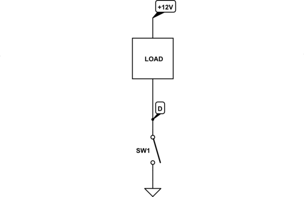
There remains the question of why the "amplified function generator" *does* produce \$V_D=+12V\$ (corresponding to \$V_L=0V\$), while your simple MOSFET switch does not. This can be explained by comparing your MOSFET switch with a simplified version of the function generator's output system. This is how the MOSFET behaves:
<!-- Begin schematic: In order to preserve an editable schematic, please
don't edit this section directly.
Click the "edit" link below the image in the preview instead. -->

<!-- End schematic -->
Here, the MOSFET is SW1, and is only able to *sink* current to ground via the load, when SW1 is closed. It is able to produce the condition \$V_D=0\$, but when SW1 is open, that MOSFET has no control over the potential at D. Contrast this with a naive representation of how the function generator behaves:
<!-- Begin schematic: In order to preserve an editable schematic, please
don't edit this section directly.
Click the "edit" link below the image in the preview instead. -->

<!-- End schematic -->
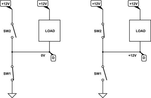
The function generator has what is known as a "push-pull" output. Like the single-switch MOSFET arrangement, it is able to sink current through SW1 to ground via the load, effectively "pulling current" from the load. Crucially, though, it is also able to *source* current *to* the load, via SW2, effectively "pushing" current into that load. This extra current sourcing ability gives it control of \$V_D\$ at all times, and can enforce both conditions \$V_D=0V\$ or \$V_D=+12V\$.
Using such a push-pull drive, I would expect \$V_D\$ to oscillate between 0V and +12V with *any* type of load, motor or resistance, because control of \$V_D\$ is never relinquished.
I called the above representation "naive" because the function generator does not employ switches. Rather, it has an analogue output stage consisting of transistors operating in a linear fashion, able to produce sinusoidal or triangular or even arbitrary output waveforms. In this application, though, where you are asking the function generator to produce a rectangular 0V or +12V waveform, my switch analogy above is a close enough representation of what's happening.
That's not to say that the waveform will be a pristine rectangle, the function generator is still fighting against a source of energy in both states, and who "wins" in the battle for control of \$V_D\$ will depend on which is "stronger", having the lowest source impedance, and which is able to respond more quickly to changes.
---
There is another quirk of behaviour for a push-pull drive that distinguishes it from a single-MOSFET arrangement. In the single switch/MOSFET scenario, when the MOSFET is off (SW1 open), the motor is effectively disconnected at one end, and is permitted to free-wheel under its own momentum.
In the push-pull arrangement of your function generator, when its output is \$V_D=+12V\$ (SW2 closed, SW1 open, above right) the motor is effectively short-circuited, having +12V applied somewhat brutally at both ends, for a potential difference \$V_L=0V\$. In this state the motor's kinetic energy is being drained rapidly (energy lost as heat in its own internal resistance), and the motor experiences *hard* braking. Therefore, with push-pull PWM, the motor alternates between phases of active acceleration and active deceleration.
In your own circuit, the motor is actively accelerated, but the only cause for deceleration is friction.
This has interesting consequences for motor speed control, in a closed loop. A mechanically unloaded motor will accelerate very rapidly, even at low PWM duty-cycle, and without any means to actively decelerate it (such as you have when using push-pull), it is disturbingly easy for motor speed to overshoot, and take an age to slow down to the desired set-point speed. This is an argument in favour of a push-pull driver, mostly referred to as a "half-bridge".