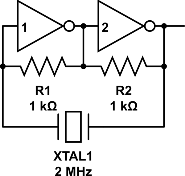
The easiest approach I have found and used is with just two inverters:
<!-- Begin schematic: In order to preserve an editable schematic, please
don't edit this section directly.
Click the "edit" link below the image in the preview instead. -->

<!-- End schematic -->
I have built this with a 74LS04 with no problem at all. It is trivial. No calculations of RC networks required. 2MHz and 4MHz both worked. I am going to experiment with a Schmitt trigger-inverter to follow to see if that makes the wave more of a rectangle.
My scope picture shows what I am getting and I use a 74LS161 counter to divide the frequency down and I see the forms are all the same: a little down spike right before the rising edge and then a bit of an up-slope of the roof of the wave. I think that's mostly determined by my use of bread board.
[![enter image description here][1]][1]
[1]: https://i.sstatic.net/RcMAZ.jpg