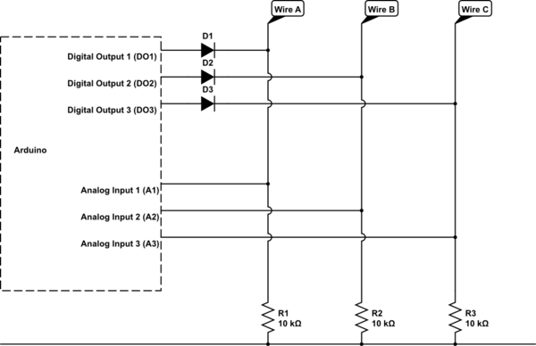
Firstly, does it really need to measure resistance? As far as I can tell, it will be a case of a contact either being open circuit or short circuit - nothing inbetween?
The advantage of microcontrollers, Arduinos and so on is they can perform operations in very quick succession, such that they appear simultaneous to the human eye.
So make the Arduino test one part at a time, in quick succession. Thus it will appear as if it has tested all 3 simultaneously.
I cannot work out what your fencing body "cord" does exactly. If you give more information on how it works, perhaps someone can design the circuit for you.
Also, what you say about the mis-wiring problem is not clear: do you want the circuit to some how know if you have mis-wired it? I can't see that being possible.
Edit:
I think I know roughly what you want now. At the least, I can give you a circuit which you can adapt.
The principle will be as per Spehro Pefhany's comment: use 6 pins from the Arduino- three digital to drive and three analog to read. So this is how that would look:
<!-- Begin schematic: In order to preserve an editable schematic, please
don't edit this section directly.
Click the "edit" link below the image in the preview instead. -->

<!-- End schematic -->
Ok, it looks like CircuitLab is giving me errors. I will come back to that circuit when it's back up. In the meantime, this is how your pseudocode for the above would look:
1. Set digital outputs DO1,DO2,DO3 as 1,0,0
2. Now read Analogue input A2.
3. If A2 is high, then wires A and B are connected. Higher value = lower resistance between wires A and B.
2. Now read Analogue input A3.
4. If A3 is high, then wires A and C are connected. Higher value = lower resistance between wires A and C.
5. Set digital outputs DO1,DO2,DO3 as 0,1,0
5. Now read Analogue input A3.
6. If A3 is high, then wires B and C are connected. Higher value = lower resistance between wires B and C.
As you can see, you now know every combination of connections between A, B and C. So in fact, some parts of the circuit above are redundant. And you do not need to read the resistances simultaneously. Steps 1-6 above can be completed within a very tiny fraction of a second - in the order of 100 microseconds. (one ten-thousandth of a second).
You can remove diode D3 and the connection to Arduino's digital output DO3. You can remove resistor R1 and Arduino's connection A1.